Splashing preventing and oily water collecting device of cooking pressure cooker

A collection device and pressure cooker technology, applied in pressure cookers, cooking utensils, household appliances, etc., can solve the problems of increasing the exhaust pressure of the pressure cooker, danger, and being unfavorable for the safe use of the pressure cooker, and achieve the effect of increasing heat energy loss.

Inactive Publication Date: 2014-05-28
戴永锋
View PDF10 Cites 0 Cited by
  • Summary
  • Abstract
  • Description
  • Claims
  • Application Information

AI Technical Summary

Problems solved by technology

In the latter technical solution, the oil and water gathered around the bonnet are sprayed out from the air duct connected to the upper part of the muffler cover, which makes it easier to increase the exhaust pressure of the pressure cooker, especially when there is an abnormal state in which the air duct is blocked, it will significantly increase The exhaust pressure of the pressure cooker is extremely unfavorable to the safe use of the pressure cooker, and the application of this technical solution has certain dangers
[0006] In a word, the existing technical solutions are not easy to popularize and apply because of the use defects or potential use safety problems, so that the existing pressure cookers are prone to problems in the cooking process and cannot be properly solved.

Method used


Image

  • Splashing preventing and oily water collecting device of cooking pressure cooker
  • Splashing preventing and oily water collecting device of cooking pressure cooker
  • Splashing preventing and oily water collecting device of cooking pressure cooker

Examples


Embodiment 1

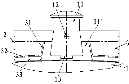
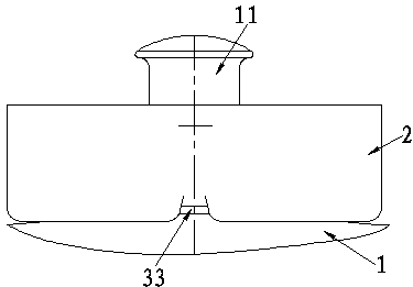
[0024] The anti-splash and oil-water collection device of the cooking pressure cooker according to Embodiment 1 of the present invention (for the structure see figure 1 , figure 2 and Figure 7 ), including a cylinder cover 2 located on the cover 1 of the pressure cooker around the pressure limiting valve to block the mixed fluid sprayed from the pressure limiting valve. The receiving groove 3 surrounding the bonnet 11 of the pressure limiting valve on 1; the receiving groove 3 is integrally connected to the bottom ends of the cylinder wall of the cylinder cover 2 and the inner ring wall 31 with a through hole 311 located inside it. The bottom of the groove 32 between the parts is composed of three parts; the minimum aperture of the above-mentioned through hole 311 is greater than the maximum outer diameter of the upper end of the bonnet 11, so that the cylinder cover 2 and the receiving groove 3 are loosely fitted on the bonnet 11 through the through hole 311. and make a s...

Embodiment 2

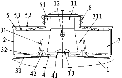
[0032] The anti-splash and oil-water collection device of the cooking pressure cooker according to the second embodiment of the present invention (for the structure see image 3 , Figure 4 and Figure 6 to Figure 8 ). On the basis of Embodiment 1 of the present invention, in order to make the function of the device of the present invention more perfect, so that it is easier to implement and apply, the following structure is further constructed, namely:

[0033] Further structure 1: the inner circumference of the above-mentioned inner ring wall 31 is provided with a sleeve shoulder 4 which is located on the pot cover 1 and surrounds the pressure limiting valve. The sleeve shoulder 4 is connected to the lower end of the pressure limiting valve sleeve 13 through the sleeve hole 41, and the sleeve There is a suitable distance between the shoulder 4 and the bottom side of the bonnet 11 for the passage of the mixed fluid; the sleeve cover 2 and the receiving groove 3 are loosely ...

Embodiment 3

[0043] The anti-splash and oil-water collection device of the cooking pressure cooker according to the third embodiment of the present invention (for the structure see Figure 5 to Figure 8 ), compared with Embodiment 2 of the present invention, its structure is different in that:

[0044] The sleeve shoulder 4 is integrally constructed with the pot cover 1 .

[0045]In the structure of the present embodiment three, the independent component, namely the cover shoulder 4, is omitted, and the matching change of the local structure on the pot cover 1 can realize the structural function of the cover shoulder 4 in the embodiment two, so that the device of the present embodiment three The structure is more compact, the use is more convenient and easy to popularize and apply.

[0046] Other configurations and corresponding functions in Embodiment 3 correspond to those described in Embodiment 1 and Embodiment 2, and will not be repeated here.

[0047] Obviously different from the pr...


PUM


Abstract

The invention provides a splashing preventing and oily water collecting device of a cooking pressure cooker. The splashing preventing and oily water collecting device comprises a cylindrical cover (2). A receiving groove (3) is formed in the lower portion of the cylindrical cover (2); the receiving groove (3) comprises the cylindrical cover (2), an inner ring wall (31) and a groove bottom (32); the cylindrical cover (2) and the receiving groove (3) sleeve the outer periphery of a valve bonnet (11) and are connected with a cooker lid (1) in a clinging manner by the groove bottom (32); the peripheral edge of the upper end of the inner ring wall (31) is lower than the lower edge of a bonnet hole (12). The splashing preventing and oily water collecting device has the advantages that splashing preventing, oily water collecting and noise reducing functions can be realized on the premise that the safety use of the pressure-cooker is unaffected; the cylindrical cover (2) and the receiving groove (3) are of integral structures, and accordingly the splashing preventing and oily water collecting device is reasonable and practical in structure, can sleeve the existing pressure cooker to be used at any time, brings convenience for cooking by the aid of the pressure cooker and is easy to popularize and apply.

Description

technical field [0001] The invention relates to an anti-splash and oil-water collection device for a cooking pressure cooker. Background technique [0002] The cooking pressure cooker (hereinafter referred to as: pressure cooker) that the public uses on the gas range or induction cooker daily, for safety needs, the pot cover of pressure cooker is provided with gravity-type pressure-limiting exhaust valve (hereinafter referred to as: pressure-limiting valve). When the pressure cooker exhausts under pressure limitation, most of the gas is ejected from the four vent holes (hereinafter referred to as: cap holes) on the gravity cap (hereinafter referred to as: valve cap) of the pressure limiting valve, and the following inconveniences are prone to occur: 1. The hot gas mixed with oil, water and fine food particles (hereinafter collectively referred to as: mixed fluid) sprayed out along the horizontal direction is easy to splash on the utensils around the pressure cooker and affec...

Claims


Application Information

Patent Timeline
Patent Type & Authority Applications(China)
IPC IPC(8): A47J27/08A47J36/00
Inventor 戴永锋
Owner 戴永锋
Why Eureka
Try Eureka