Detachable high-voltage connection structure and high-voltage connector

A high-voltage connector, detachable technology, applied in the direction of connection, connecting device parts, electrical components, etc., can solve the problems of unrepairable products, difficult slotting, time-consuming and labor-intensive, etc.

Active Publication Date: 2014-05-28
中国电子科技集团公司第四十研究所
View PDF7 Cites 7 Cited by
  • Summary
  • Abstract
  • Description
  • Claims
  • Application Information

AI Technical Summary

Problems solved by technology

[0003] However, it is necessary to ensure the sealing performance between the various parts of this kind of socket assembly or pin assembly, so the matching size and accuracy requirements must be ensured during processing. Because the cavity needs to be slotted, slotting is more difficult in the design of the connector. In addition, the above-mentioned structure often uses potting treatment to achieve high voltage resistance at the tail. Once the product after potting treatment is damaged, it cannot be repaired.
[0004] The high-voltage connector includes a socket and a plug. The socket is equipped with several jack components of the above structure, and the plug is built with the pin component of the above structure. The plug and the socket are mated correspondingly, which can conveniently realize the connection between high-voltage equipment or internal modules of the equipment. High-voltage connection, but it is integrally molded during processing, which is difficult to process, high in cost, and poor in interchangeability; and because of the characteristics of transmitting high-voltage signals, after a high-voltage wire or several high-voltage wires break down and fail, Since the discharge channel after breakdown cannot be repaired, the entire set of connectors must be replaced, which is time-consuming, laborious, and costly

Method used


Image

  • Detachable high-voltage connection structure and high-voltage connector
  • Detachable high-voltage connection structure and high-voltage connector
  • Detachable high-voltage connection structure and high-voltage connector

Examples


Embodiment Construction

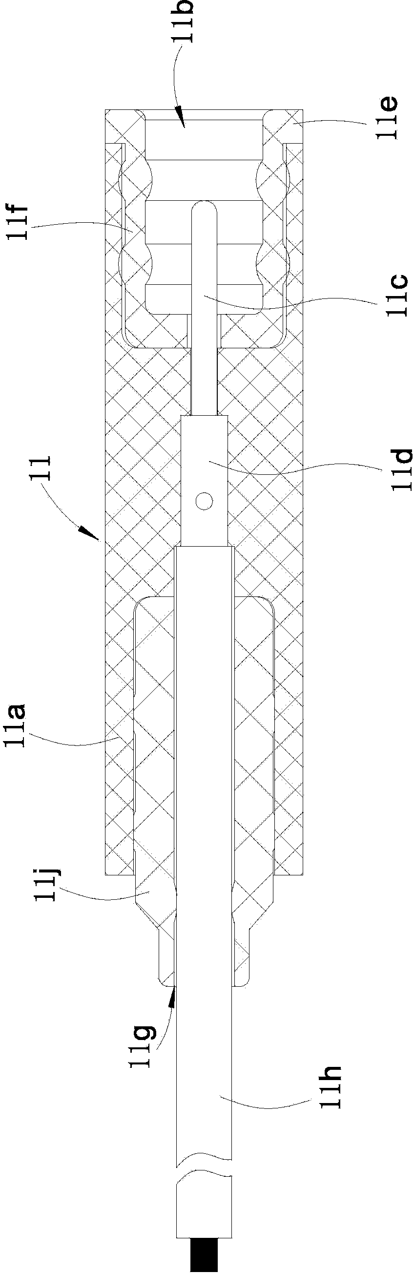
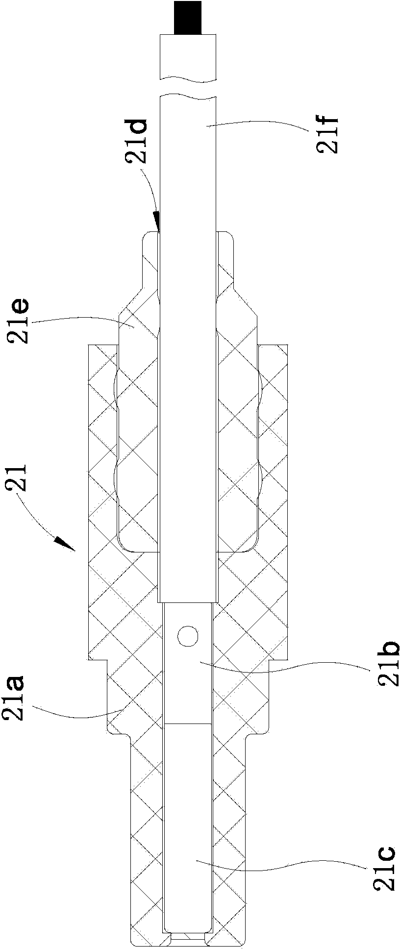
[0022] Such as Figures 1 to 2 as shown,

[0023] This structure includes jack assembly 21 and pin assembly 11;

[0024] The pin assembly 11 includes a pin housing 11a, a pin 11c, a first tail sleeve 11j and a sealing sleeve 11f. The material used for the pin housing 11a is insulating hard engineering plastic, and the front end of the pin housing 11a is provided with a concave Slot 11b, the middle part of the pin housing 11a has a mounting groove matching the shape of the pin 11c, so that the pin 11c is horizontally installed in the mounting groove, the rear part of the pin 11c is the first connecting end 11d, and the front end of the pin 11c extends into the concave In the groove 11b, an elastic insulating sealing sleeve 11f is set inside the groove 11b. The material of the sealing sleeve 11f is silicon rubber. The rear end of the pin 11c is closed and set on the pin 11c. The length of the pin 11c is such that its front end is located in the middle section of the sealing sl...


PUM


Abstract

The invention discloses a detachable high-voltage connection structure, comprising a jack component and a contact pin component, wherein the contact pin component at least comprises a contact pin shell, a contact pin and a sealing sleeve; a groove is formed in the front end face of the contact pin shell; the middle part of the contact pin shell is provided with a mounting trough matched with a contact pin in shape; the contact pin is mounted in the mounting trough, a first wiring duct is formed in the rear part of the contact pin shell; a first high-voltage wire is connected with the contact pin via the first wiring duct; the jack component at least comprises a jack shell and a jack member; a second wiring duct is formed in the front part of the jack shell; a second high-voltage wire is connected with the jack member via the second wiring duct; a first tail sleeve is mounted on in the side wall of the first wiring duct in a sleeved manner; a second tail sleeve is mounted in the side wall of the second wiring duct in a sleeved manner. The first tail sleeve greatly improves the voltage-withstanding effect of the rear part of the contact pin component, can be freely inserted and pulled out and is convenient to replace; the second tail sleeve greatly improves the voltage-withstanding effect of the front part of the jack component, can be freely inserted and pulled out and is convenient to replace.

Description

technical field [0001] The invention relates to a detachable high-voltage connection structure; the invention also relates to a high-voltage connector. Background technique [0002] At present, the high-voltage connection structure of high-voltage electrical connectors usually includes a jack assembly and a pin assembly; the pin assembly includes at least a pin housing, a pin and a sealing sleeve, and the front end of the pin housing has a groove, and the pin There is a mounting groove matching the shape of the pin in the middle of the housing. The pin is installed in the mounting groove. The rear part of the pin is the first connection end. The front end of the pin passes through the sealing sleeve and extends into the groove. The groove is set with Elastic insulating sealing sleeve, the front end of the sealing sleeve is open and has an everted flange matching the groove, the rear end of the sealing sleeve is closed and fitted on the pin, the length of the pin is such that...

Claims


Application Information

Patent Timeline
Patent Type & Authority Applications(China)
IPC IPC(8): H01R13/436H01R13/502H01R13/518H01R13/52
Inventor 余海洋彭长江王小波王强彭光辉刘敏
Owner 中国电子科技集团公司第四十研究所
Why Eureka
Try Eureka