
Lamp with replaceable ornament
A technology for lamps and decorative parts, applied in the field of lamps with replaceable decorative parts, can solve the problems of time and labor costs, troubles, inability to adjust the color of lamp products and light field, etc.
- Summary
- Abstract
- Description
- Claims
- Application Information
AI Technical Summary
Problems solved by technology
Method used
Image

Examples
Embodiment Construction
[0046] Before the present invention is described in detail, it should be noted that in the following description, similar components are denoted by the same numerals.
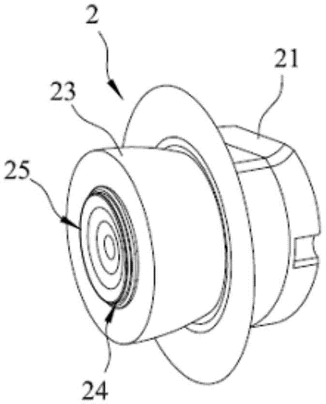
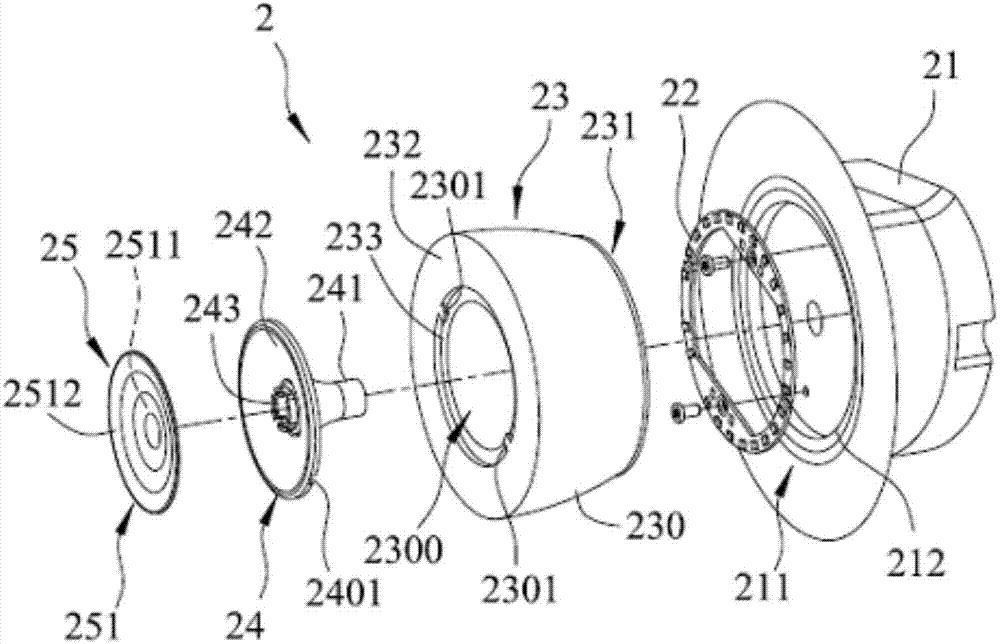
[0047] refer to figure 2 and image 3 , is the first preferred embodiment of the lamp 2 with replaceable decorative parts of the present invention, including a base 21, a light emitting module 22 arranged on the base 21, a lens unit 23 covered on the light emitting module 22, and a penetrating A fixing unit 24 in the lens unit 23 , and a decoration unit 25 replaceably installed on the fixing unit 24 and located in front of the lens unit 23 .
[0048] The base 21 includes a connection surface 211 facing the light emitting module 22 , and an annular protruding portion 212 disposed on the connection surface 211 and capable of connecting with the lens unit 23 .
[0049] refer to image 3 The lens unit 23 includes a lens body 230 surrounding a through hole 2300 . The lens body 230 covers the light emitting modul...
PUM
 Abstract
Description
Claims
Application Information