Liquid fuel gasification burner

A liquid fuel, burner technology, applied in the direction of burner, combustion method, combustion type, etc., can solve the problems of liquid leakage, high pressure, bad, etc., to achieve uniform fire dispersion, good heating effect, and improve thermal efficiency.

Inactive Publication Date: 2014-10-01
邹鑫
View PDF7 Cites 1 Cited by
  • Summary
  • Abstract
  • Description
  • Claims
  • Application Information

AI Technical Summary

Problems solved by technology

However, this kind of combustion equipment without vaporized liquid fuel is not ideal for the simple heating of liquid fuel; on the one hand, the mixing of air and liquid fuel is not sufficient, resulting in insufficient combustion of liquid fuel, and the utilization of liquid fuel

Method used


Image

  • Liquid fuel gasification burner

Examples


Embodiment 1

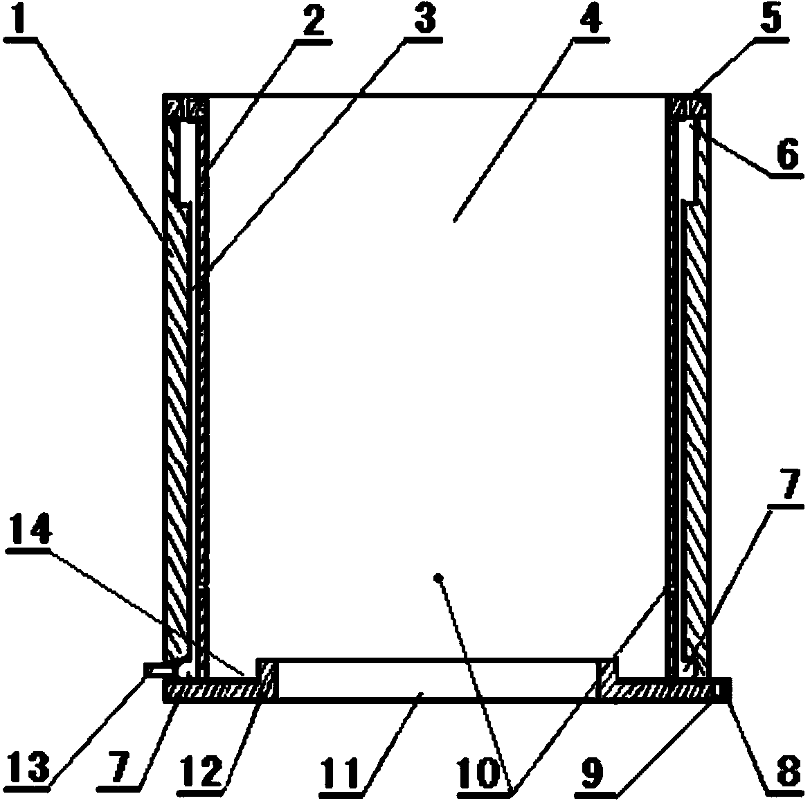
[0029] Such as figure 1 As shown, the burner is a tube burner, which includes a casing 1, a heat transfer layer 2, a gasification interlayer 3, a gas hole 5, an air storage tank 6, a liquid distribution tank 7, a liquid fuel hole 10, an air port 11 and Liquid supply connection pipe 13; the shell 1 is connected with the two ends of the heat transfer layer 2 to form a gasification interlayer 3, the interlayer thickness of the gasification interlayer 3 is 0.04cm, and the middle of the tube is a heat supply chamber; the bottom of the burner Bottom plate 12 is arranged at the end, and bottom plate 12 is provided with anti-oil spill ring groove 14, and the middle of anti-oil spill ring groove 14 is air port 11, and the outer circle of bottom plate 12 is provided with 3 fixed ears 8; Said fixed ears 8 and support feet use bolt holes 9 is fixed and installed in the furnace hall; the inner ring of the upper section of the shell 1 is provided with a square annular gas storage tank 6, an...

Embodiment 2

[0031] Such as figure 1 As shown, the burner is a tube burner, which includes a casing 1, a heat transfer layer 2, a gasification interlayer 3, a gas hole 5, an air storage tank 6, a liquid distribution tank 7, a liquid fuel hole 10, an air port 11 and The liquid supply connection pipe 13; the two ends of the shell 1 and the heat transfer layer 2 are connected to form a gasification interlayer 3, the interlayer thickness of the gasification interlayer 3 is 0.07cm, and the middle of the tube is a heat supply chamber; the bottom of the burner Bottom plate 12 is arranged at the end, and bottom plate 12 is provided with anti-oil spill ring groove 14, and the middle of anti-oil spill ring groove 14 is air port 11, and the outer circle of bottom plate 12 is provided with 4 fixed ears 8; Described fixed ear 8 is provided with bolt hole 9; The inner ring of the upper part of the casing 1 is provided with a square annular gas storage tank 6, and the end of the casing 1 is provided with...

Embodiment 3

[0033] Such as figure 1 As shown, the burner is a tube burner, which includes a casing 1, a heat transfer layer 2, a gasification interlayer 3, a gas hole 5, an air storage tank 6, a liquid distribution tank 7, a liquid fuel hole 10, an air port 11 and Liquid supply connection pipe 13; the shell 1 is connected with the two ends of the heat transfer layer 2 to form a gasification interlayer 3, the interlayer thickness of the gasification interlayer 3 is 0.09cm, and the middle of the tube is a heat supply chamber; the bottom of the burner Bottom plate 12 is arranged at the end, and bottom plate 12 is provided with anti-oil spill ring groove 14, and the middle of anti-oil spill ring groove 14 is air port 11, and the outer circle of bottom plate 12 is provided with 4 fixed ears 8; Described fixed ear 8 is provided with bolt hole 9; The inner ring of the upper part of the casing 1 is provided with a square annular gas storage tank 6, and the end of the casing 1 is provided with mor...


PUM


Abstract

The invention discloses a liquid level gasification burner. The liquid level gasification burner comprises a shell, a heat transfer layer, a gasification interlayer, a fuel gas hole, a gas storage tank, a liquid distribution tank, a fuel liquid hole, an air opening and a feed liquid connecting pipe, wherein a tubular burner with the gasification interlayer is constituted by the connection of the shell and the heat transfer layer, and a bottom plate is arranged at the bottom of the tubular burner; the gas storage tank is arranged on an inner ring of upper section of the shell, the fuel gas hole is formed in the end of the shell, the liquid distribution tank is arranged on the inner ring of the upper section of the shell, and the feed liquid connecting pipe is arranged on the shell located on the liquid distribution tank; the fuel liquid hole is formed the lower section of the heat transfer layer; and the air opening is formed in the middle of the bottom plate. According to the liquid level gasification burner, an atomized liquid fuel of the fuel liquid hole is arranged at the lower section of the heat transfer layer, so that the liquid fuel entering from the gasification interlayer can be fully gasified, the flue flame can be formed, the liquid fuel can be fully burnt, the thermal efficiency can be improved, the fuel can be saved, and the fire can be uniformly dispersed; and moreover, the environment is not polluted, and the safety performance is good, therefore, the burner is applied to boiler equipment and kitchen stoves with organic liquid fuel, and has good economic benefit, social benefit and ecological benefit.

Description

technical field [0001] The invention belongs to the technical field of liquid fuel combustion equipment, and relates to a liquid fuel gasification burner. Background technique [0002] Conventionally used liquid fuel combustion equipment mainly includes a main body of a combustion furnace. A combustion chamber is formed inside the main body. The upper end of the combustion chamber is a flame opening, and the lower end is connected to a gas source or liquid fuel. When in use, the valve is opened, and fuel and air are delivered to the combustion chamber at the same time. The fuel and air are mixed in the combustion chamber and then burned. The burning flame radiates to the material to be heated in the furnace of the equipment to heat or melt the material. However, this kind of combustion equipment without vaporized liquid fuel is not ideal for the simple heating of liquid fuel; on the one hand, the mixing of air and liquid fuel is not sufficient, resulting in insufficient comb...

Claims


Application Information

Patent Timeline
IPC IPC(8): F23D11/00F23D11/44F23D11/36
Inventor 邹鑫卢颖谢美萱
Owner 邹鑫
Why Eureka
Try Eureka