Scanning head of scanning tunneling microscope

A scanning tunnel and scanning head technology, applied in scanning probe microscopy, scanning probe technology, measuring devices, etc., can solve the problems of inconvenient replacement of the mechanical arm and damage to the scanning head, etc.

Inactive Publication Date: 2014-11-12
INST OF PHYSICS - CHINESE ACAD OF SCI
View PDF6 Cites 9 Cited by
  • Summary
  • Abstract
  • Description
  • Claims
  • Application Information

AI Technical Summary

Problems solved by technology

However, the design of the Besocke Type STM scanning head that is widely used now makes it inconvenient to use a ...

Method used


Image

  • Scanning head of scanning tunneling microscope
  • Scanning head of scanning tunneling microscope
  • Scanning head of scanning tunneling microscope

Examples


Embodiment Construction

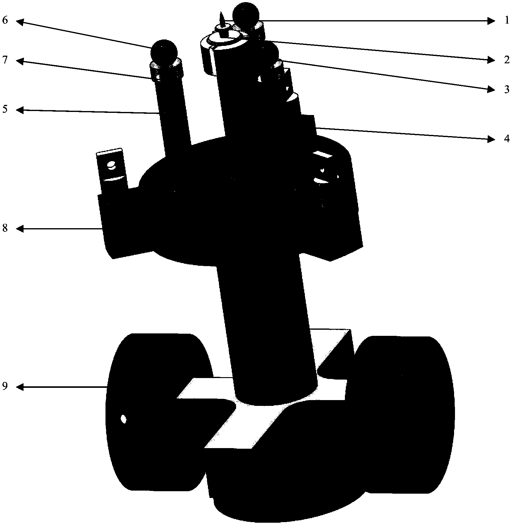
[0018] like figure 1 The illustrated embodiment shows a Besocke Type scanning tunneling microscope scan head according to the invention. The scanning head includes: needle point 1, needle point support 2, needle point support base 3, Z piezoelectric ceramic tube 4, X-Y piezoelectric ceramic tube 5 (only one of the three is labeled in the figure), tungsten ball 6 (in the figure Only one of the three is numbered), thick sapphire 7 (only one of the three is numbered in the figure), scanning head base 8, shock absorbing device 9.

[0019] Tip 1 is an electrochemically etched tungsten or silver tip.

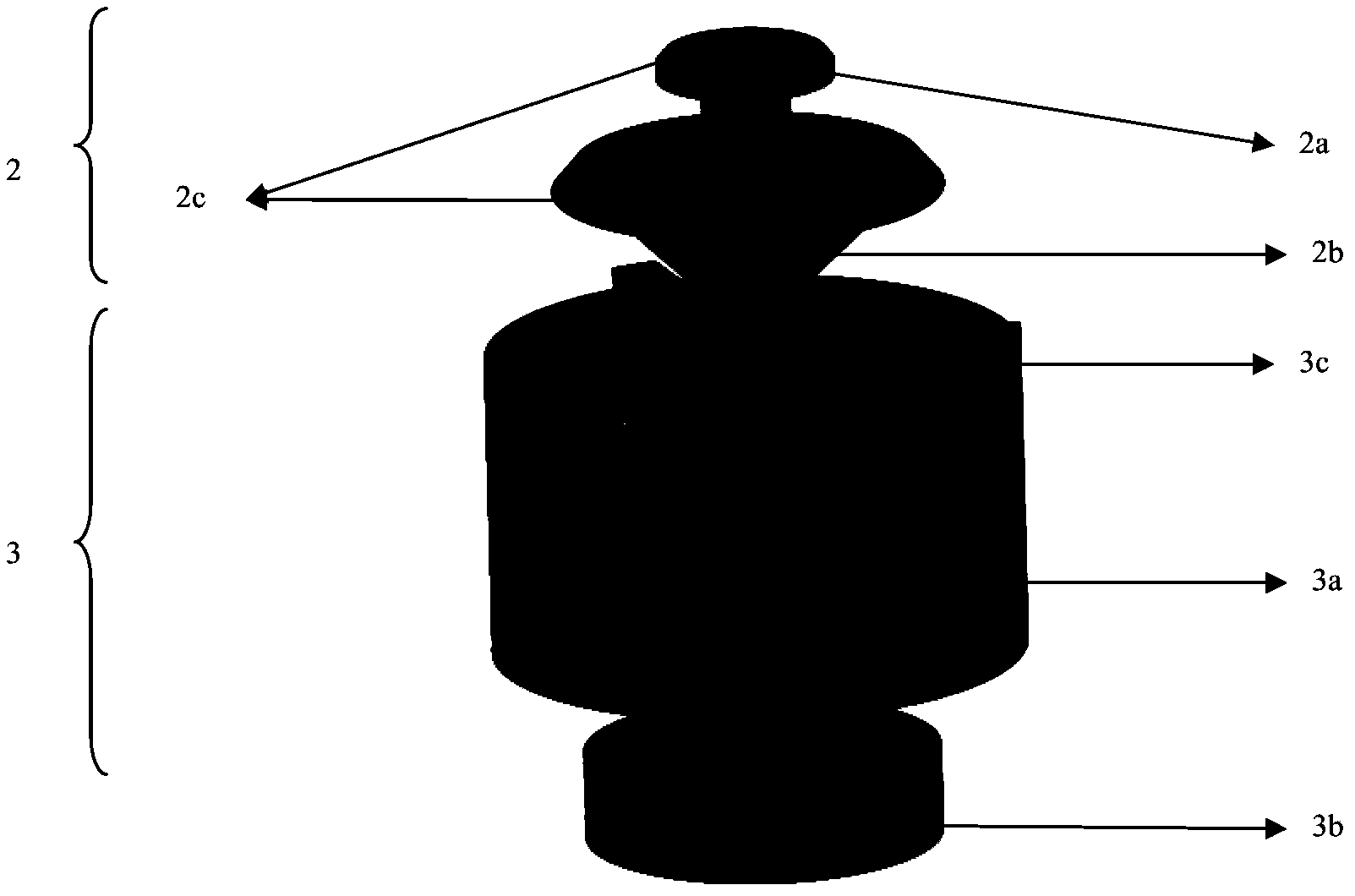
[0020] The needle point holder 2 is used to fix the needle point 1. In this embodiment, the needle point 1 is fixed to the cylindrical through hole 2a in the middle of the needle point holder 2 by conductive glue or solder (refer to figure 2 )middle. The needle point support 2 and the needle point support base 3 are detachable. The needle point support base 3 is glued on the Z p...


PUM


Abstract

The invention provides a scanning head of a scanning tunneling microscope. The scanning head comprises a needle point bracket for fixing a needle point and a needle point bracket base comprising a supporting structure, wherein the needle point bracket is combined with the needle point bracket base through separable binding force. By the adoption of the scanning head of the scanning tunneling microscope, the needle point of the scanning head can be safely and quickly replaced in a vacuum environment, and an existing vacuum environment can not be damaged.

Description

technical field [0001] The invention relates to the field of scanning tunneling microscopes, in particular to a scanning tunneling microscope scanning head. Background technique [0002] Scanning tunneling microscope (STM) is an important instrument that can use tunneling current to measure surface topography. The scanning head is the core part of scanning tunneling microscope that can collect data and manipulate atoms. Among them, the tip of the scanning head is often damaged in the experiment, so replacing the tip is a problem that often needs to be faced in STM experiments. Replacing the needle tip in an atmospheric environment can be easily achieved with tweezers. However, in ultra-vacuum experiments, taking out the needle tip and replacing it will destroy the vacuum environment that is hard to obtain. Therefore, in an ultra-high vacuum environment, a manipulator is generally used to replace the needle tip of the scanning head. However, the design of the widely used Be...

Claims


Application Information

Patent Timeline
IPC IPC(8): G01Q60/10G01Q60/16
Inventor 宫会期王劲川孙丽欢董立颜世超谢楠单欣岩郭阳陆兴华
Owner INST OF PHYSICS - CHINESE ACAD OF SCI
Why Eureka
Try Eureka