Application method of electronic fence

A technology of electronic fence and application method, which is applied in the direction of electrical components, transmission systems, and services based on location information, etc., which can solve problems affecting the fairness of electronic fences, increase the computing power of the client, and poor stability, and achieve accurate information transmission Timely, stable and efficient operation, guaranteed results

Inactive Publication Date: 2014-12-10
JIANGSU DIGITAL DNA TECH CO LTD
View PDF5 Cites 5 Cited by
  • Summary
  • Abstract
  • Description
  • Claims
  • Application Information

AI Technical Summary

Problems solved by technology

[0003] The electronic fences of existing positioning equipment operators have been used for a long time, but these electronic fences basically adopt the electronic fence technology on the device side, that is to say, among the clients that send the location of the electronic fence, the customer When the terminal collects WGS coordinates, it compares with the position of the electronic fence in the device to determine whether the triggering condition is met. In this way, in the traditional electronic fence application, the process of comparison and judgment is handed over to the client. On the one hand, the calculation of the client is invisible. The second is to delegate the comparison and judgment process to the client, the result is easily modified and forged, which affects the fairness of the use of the electronic fence; the third is for the process of decentralizing the location of the electronic fence, the server needs to rely on the network such as the cellular digital network to transmit to the client end, the stability is poor, and there are many failure rates; the fourth is to delegate the comparison and judgment process to the client, which will involve the maintenance of the client in the future maintenance process, which is very inconvenient

Method used


Image

  • Application method of electronic fence

Examples


Embodiment Construction

[0028] The specific implementation manners of the present invention will be further described in detail below in conjunction with the accompanying drawings.

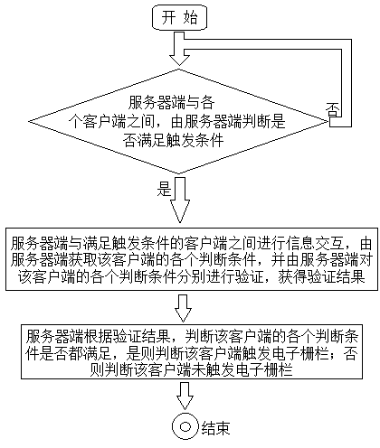
[0029] like figure 1 As shown, the present invention designs an electronic fence application method, including a server and at least one client, and an electronic fence is formed between the server and each client through an electronic fence condition, and the electronic fence condition includes a trigger condition and at least one judgment condition , the server-side preset trigger conditions and various judgment conditions, the application method specifically includes the following steps:

[0030] Step 01. Between the server and each client, the server judges whether the trigger condition is satisfied, if yes, enter the next step, otherwise continue to step 01;

[0031] Step 02. Information interaction is carried out between the server and the client satisfying the trigger condition, the server obtains each judgment c...


PUM


Abstract

The invention relates to an application method of an electronic fence, a judgment and verification process between a client and an electronic fence condition rises to be carried out at the server side, and the server side judges and verifies whether the client meets the electronic fence condition, on the one hand, the operational capability of the client is cancelled, so that the operating efficiency of the whole electronic fence is higher; secondly, the judgment and verification process rises to the server side, so that accuracy and justice of a result are guaranteed; thirdly, the judgment and verification process rises to the server side, so that the influence of a network on a process of transferring the electronic fence condition to a lower level by the server side is avoided, and thus the whole electronic fence has more stable and efficient operation; and fourthly, the judgment and verification process rises to the server side so as to be effectively convenient for future maintenance of the electronic fence.

Description

technical field [0001] The invention relates to an electronic fence application method. Background technique [0002] The electronic fence is a virtual closed area built on the WGS (World Geodetic System, world geodetic coordinate system). The electronic fence can be used to monitor whether some positioning equipment using GPS has passed the specified location. When the positioning equipment passes through the electronic fence, it will send an alarm message, which will be sent to the network management system or business statistics system by processing the alarm message. in business management. Application scenarios such as traffic control, fleet management, vehicle rescue, power repair, 120 first aid and other business tracking. [0003] The electronic fences of existing positioning equipment operators have been used for a long time, but these electronic fences basically use the electronic fence technology on the device side, that is to say, among the clients that send th...

Claims


Application Information

Patent Timeline
IPC IPC(8): H04L29/08H04W4/02
Inventor 陈祥伟刘南杰
Owner JIANGSU DIGITAL DNA TECH CO LTD
Why Eureka
Try Eureka