Brake pulling device used for cart

A trolley and push rod technology, applied in trolleys, trolley accessories, motor vehicles, etc., can solve problems such as insufficient labor saving, achieve the effects of small installation space, increased distance, and improved use effects

Inactive Publication Date: 2014-12-24
NINGBO HAISHU TIANHUA PROD DESIGN CO LTD
View PDF7 Cites 3 Cited by
  • Summary
  • Abstract
  • Description
  • Claims
  • Application Information

AI Technical Summary

Problems solved by technology

However, this device fails to change the fact that the narrow part of the eccentric wheel is subject to a relatively large pulling force, and the place where the force is applied is relatively close to the rotating shaft during the rotation, which is not labor-saving enough, so the structure of the device needs to be further improved

Method used


Image

  • Brake pulling device used for cart
  • Brake pulling device used for cart
  • Brake pulling device used for cart

Examples


Embodiment Construction

[0027] The present invention will be further described in detail below in conjunction with the accompanying drawings and embodiments.

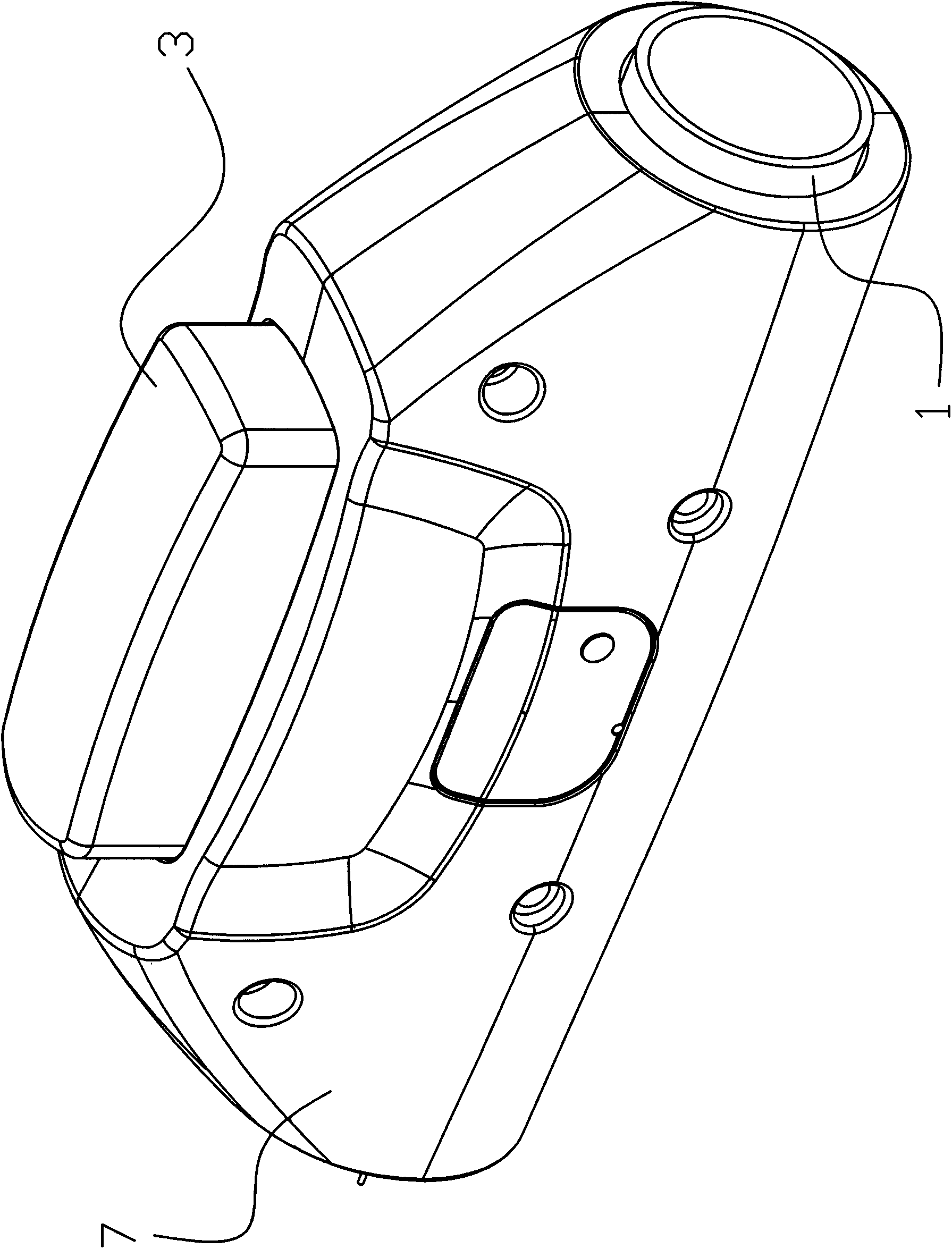
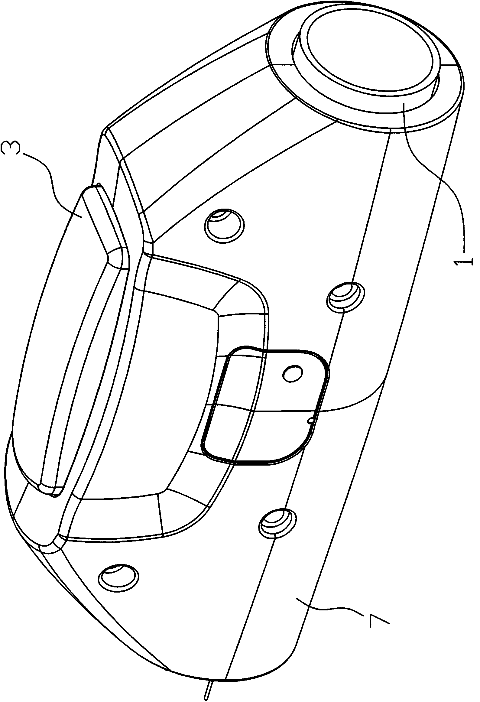
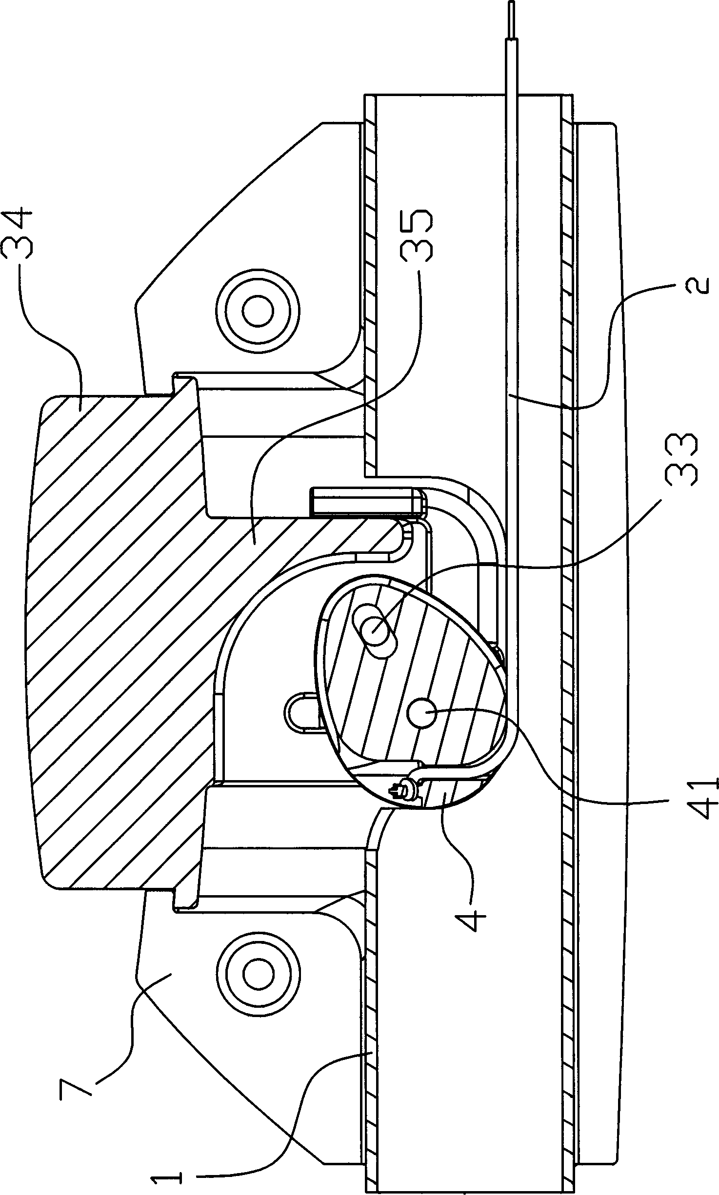
[0028] Such as Figure 1 to Figure 12As shown, the brake pulling device used on the cart in this embodiment includes a pressing part installed on the push rod 1 of the cart, and a pull cord 2 for controlling the braking of the cart is arranged in the pressing part, and the pressing part It includes a pressing block 3 and an eccentric wheel 4 arranged vertically and eccentrically rotatable. The eccentric wheel 4 is arranged in the inner cavity of the push rod 1 through an eccentric shaft 41. The two ends of the eccentric shaft 41 are connected to the push rod The corresponding side surfaces on both sides of the rod 1 are fixed, and the pressing block 3 can be inserted into the inner cavity of the push rod 1 so as to move up and down. The concave cavity 32 that the wheel 4 extends into, the eccentric wheel 4 stretches into the concave cavity 32...


PUM


Abstract

The invention discloses a brake pulling device used for a cart. The brake pulling device used for the cart comprises a pressing part arranged on a push rod (1) of the cart; a digging rope (2) is arranged in the pressing part; the pressing part comprises a pressing block (3) and an eccentric wheel (4); the eccentric wheel (4) can be eccentrically and rotatably arranged in the inner chamber of a push rod (1) through an eccentric shaft (41); both ends of the eccentric shaft (41) are respectively fixed to side faces which correspond to both sides of the push rod (1); the pressing block (3) is located in the inner chamber of the push rod (1); a strip-shaped chamber (31) is vertically formed in the pressing block (3); a concave chamber (32) is formed in the lower part of the pressing block (3); the eccentric wheel (4) extends into the concave chamber (32), and is movably connected with the pressing block (3); the eccentric shaft (41) of the eccentric wheel (4) is located at the position of the strip-shaped chamber (31) of the pressing block (3); the digging rope (2) is wound on the bottom face of the eccentric wheel (4) and passes through a fastener hole (43) of the eccentric wheel (4) so as to be fixed to the end face of the fastener hole (43), and the pressing block (3) is provided with a locking mechanism. The brake pulling device used for the cart, disclosed by the invention, has the advantages that the operation is labor-saving and convenient, the structure is firm and compact, and the service life is long.

Description

technical field [0001] The invention relates to the technical field of brake device manufacturing, in particular to a brake pull device used on a trolley. Background technique [0002] A Chinese utility model patent with the patent number CN200520097983.1 titled "Brake Device for Luggage Carts" discloses a brake device for luggage carts. device, the other end of the brake line is connected to the eccentric wheel, and the brake line is drawn out behind the eccentric wheel. Because the utility model uses the brake line to surround the eccentric wheel and lead out, it changes the stress structure and direction of the eccentric wheel, and then solves the problem that the eccentric wheel is not easy to break. However, this device fails to change the fact that the narrow part of the eccentric wheel is subjected to a relatively large pulling force, and the place where the force is applied is relatively close to the rotating shaft during the rotation, which is not labor-saving enou...

Claims


Application Information

Patent Timeline
Patent Type & Authority Applications(China)
IPC IPC(8): B62B5/04B62B5/00
Inventor 茅鸿勇
Owner NINGBO HAISHU TIANHUA PROD DESIGN CO LTD
Why Eureka
Try Eureka