

Electroplating hanger
A hanger and quantity technology, applied in the direction of electrolysis process, electrolysis components, etc., can solve the problems that cannot meet the needs of production, achieve the effect of strong versatility, improve work efficiency and product yield, and avoid slot dropping
Inactive Publication Date: 2014-12-24
天津市滨海新区众源电镀有限公司
View PDF0 Cites 0 Cited by
- Summary
- Abstract
- Description
- Claims
- Application Information
AI Technical Summary
Problems solved by technology
With the diversity of electroplating products and different weights and specifications, traditional general-purpose racks often cannot meet the needs of production
Method used
View moreImage
Smart ImageViewing Examples

Examples
Embodiment Construction
[0019] For further illustrating the present invention, now cooperate with accompanying drawing to elaborate:
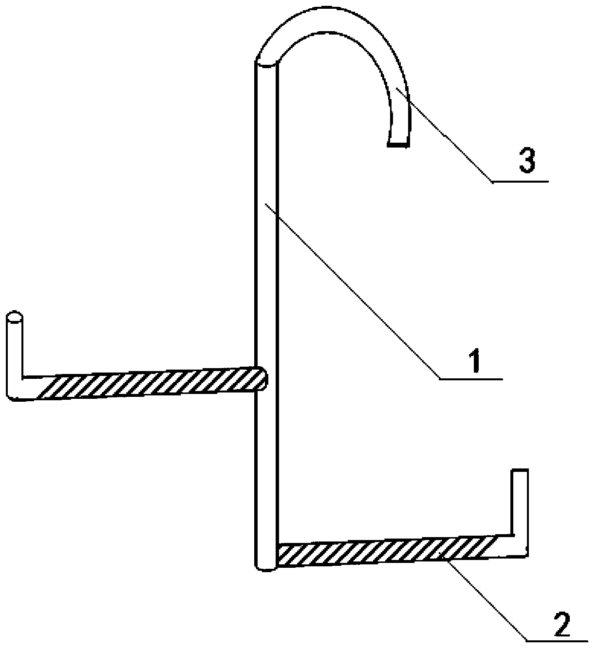
[0020] Such as figure 1 As shown, the electroplating hanger includes a main rod 1 and a support rod 2 made of metal brass, the upper end of the main rod 1 is provided with a hook 3, and the number of the support rods 2 is 2, which are welded vertically Fixed on both sides of the main pole 1, the end of the pole 2 is hooked upwards to form a flat L-shaped structure. The outer layer of the pole 2 is provided with thread-shaped protrusions. The pole 2 The outer surface of the non-contact part with the parts to be electroplated is also coated with an anti-corrosion insulating paint layer.
Login to View More PUM
 Abstract
The invention provides an electroplating hanger. The electroplating hanger comprises a main rod and a branch rod, wherein a hook is arranged at the upper end of the main rod; the branch rod and the main rod are vertically fixed by welding; the tail end of the branch rod is upwards hooked, and is of a horizontal L-shaped structure. The electroplating hanger is simple in structure and strong in universality; the upwards hooked structure of the tail end of the branch rod is especially suitable for processing a ring-shaped part; threaded bulges are arranged on the outer layer of the branch rod, so that the electroplated parts are more stable to suspend, the electroplated parts are effectively prevented from generating a slot dropping phenomenon, and the working efficiency and the product yield are greatly improved, and thus, the electroplating hanger is suitable for the needs of large-scale industrial production.
Description
technical field [0001] The invention relates to an electroplating tool, in particular to a hanging tool for electroplating. Background technique [0002] Electroplating is the process of plating a thin layer of other metals or alloys on the surface of certain metals using the principle of electrolysis. It uses electrolysis to attach a layer of metal film to the surface of metal or other materials to prevent corrosion. A process that improves wear resistance, conductivity, light reflection, and aesthetics. [0003] During electroplating, the plated metal or other insoluble materials are used as the anode, and the workpiece to be plated is used as the cathode, and the cations of the plated metal are reduced on the surface of the workpiece to be plated to form a coating. In order to eliminate the interference of other cations and make the coating uniform and firm, it is necessary to use a solution containing metal cations as the electroplating solution to keep the concentratio...
Claims
Login to View More Application Information
Patent Timeline
 Patent Type & AuthorityApplications(China)
IPC IPC(8): C25D17/08
Inventor冯长福
Owner天津市滨海新区众源电镀有限公司