Electronic type electric energy meter

An electronic, electric energy meter technology, applied in the direction of measuring electric variables, measuring devices, instruments, etc.

Inactive Publication Date: 2015-02-11
SUZHOU KELANCI ELECTRONICS SCI & TECH
View PDF2 Cites 2 Cited by
  • Summary
  • Abstract
  • Description
  • Claims
  • Application Information

AI Technical Summary

Problems solved by technology

[0004] The technical problem solved by the present invention: the electric energy generated by the user's own power generation system and incorporated into the power grid can be exchanged for the electric energy of the same amount of power grid. In this way, a method that can not only measure the electric energy consumed by the user (that is, positive electric energy) but also measure the user Bi-directional energy meter for electrical energy fed back to the grid

Method used


Image

  • Electronic type electric energy meter
  • Electronic type electric energy meter

Examples


Embodiment Construction

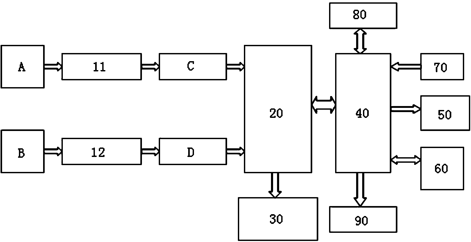
[0026] Such as figure 1 As shown, an electronic electric energy meter includes a front-end circuit conditioning module, an electric energy metering chip 20, an LED indicator module 30, a micro control unit 40, a display module 50, a communication module 60, a keyboard control module 70, a clock module 80, and a memory 90 , Power module. The front-end circuit conditioning module is connected to the electric energy metering chip 20, the LED indicator module 30 is connected to the electric energy metering chip 20, the micro control unit 40 is connected to the electric energy metering chip 20, the display module 50, the communication module 60, the keyboard The control module 70 , the clock module 80 and the memory 90 are respectively connected with the micro control unit 40 . The front-end circuit conditioning module includes an electronic current-type voltage transformer 11, a current transformer 12, and a precision resistance circuit.

[0027] Wherein, the electric energy met...


PUM


Abstract

The invention discloses an electronic type electric energy meter. The electronic type electric energy meter comprises a front end circuit conditioning module, an electric energy metering chip (20), an LED (light emitting diode) indicating module (30), a micro-control unit (40), a display module (50), a communication module (60), a key control module (70), a clock module (80), a memory (90) and a power supply module, wherein the front end circuit conditioning module is connected with the electric energy metering chip (20); the LED indicating module (30) is connected with the electric energy metering chip (20); the micro-control unit (40) is connected with the electric energy metering chip (20); the display module (50), the communication module (60), the key control module (70), the clock module (80) and the memory (90) are connected with the micro-control unit (40). Through the electric energy meter provided by the invention, purposes of electric parameter measurement, displaying and acquiring treatment for electric energy can be realized.

Description

Technical field: [0001] The invention relates to electric energy metering technology, in particular to an electronic electric energy meter. Background technique: [0002] In order to implement sustainable development and solve the contradiction between environment and development, many countries in the world are actively exploring green energy to reduce environmental pollution and loss of non-renewable resources by traditional power generation methods, or to save investment, reduce energy consumption, and improve system security. and flexibility, adopt the power supply method combining large power grid system and distributed power generation system. After a systematic and scientific design and a reasonable planning of the electric energy market, the distributed small-scale power supply system can not only solve the energy problems of residents but also feed back the surplus electric energy to the grid to realize electricity compensation, thereby reducing the burden on the po...

Claims


Application Information

Patent Timeline
Patent Type & Authority Applications(China)
IPC IPC(8): G01R22/06
Inventor 马治远吴秋轩喻航黄敏峰吴永鑫
Owner SUZHOU KELANCI ELECTRONICS SCI & TECH
Why Eureka
Try Eureka