Gate type plate shearing machine

A shearing machine and gate type technology, which is applied in shearing machine equipment, shearing devices, accessories of shearing machines, etc. Machine difficulties and other problems, to ensure the effect of cutting quality

Active Publication Date: 2015-04-22
NANJING SHENGDA HEAVY IND MACHINERY
View PDF6 Cites 6 Cited by
  • Summary
  • Abstract
  • Description
  • Claims
  • Application Information

AI Technical Summary

Problems solved by technology

[0011] 3. As mentioned above, because the overall structure of the front fulcrum of the existing gate-type shearing machine is relatively large, the front fulcrum and the guide rail of the front fulcrum cannot be placed on the same plane as the side plate of the knife holder, and the front guide rail 26 can only be placed on The vertical plate of the tool post that deviates from the side plate of the tool post, that is to say, viewed from the front of the gate shears, the front fulcrum is not in the plane of the side plate of the tool post where the upper and lower fulcrums of the rear are located
[0012] 4. The three fulcrums of the existing gate-type shearing machine structure are all above the cutting edge of the lower blade, and its position is too high, which leads to the high connection position of the oil cylinder and the knife holder, so the oil cylinder can only be installed at a position higher than the frame. position, which resulted in a substantial increase in the height of the machine
The tool holder will float when changing the shear angle and adjusting the gap. The existing connection method between the oil cylinder, the frame and the tool holder cannot be optimal in terms of degrees of freedom, strength and repeat positioning accuracy.
Large gate shears are more difficult

Method used


Image

  • Gate type plate shearing machine
  • Gate type plate shearing machine
  • Gate type plate shearing machine

Examples


Embodiment Construction

[0029] This technology is a gate-type shearing machine with simple blade clearance adjustment, high precision, small overall structure of the front fulcrum, simple structure of the whole machine and low cost.

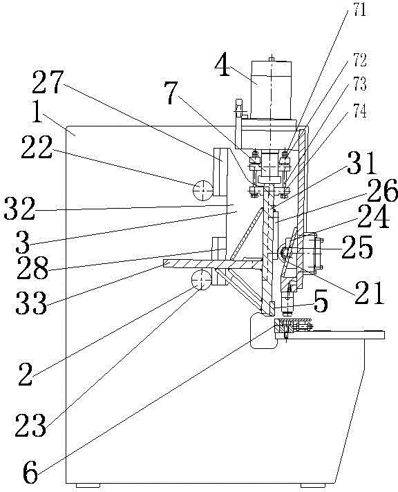
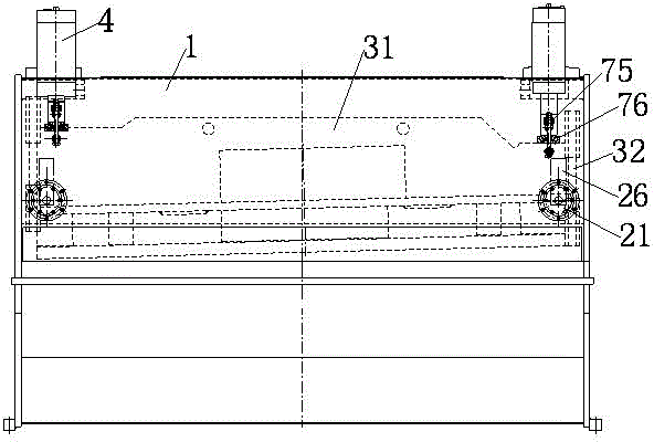
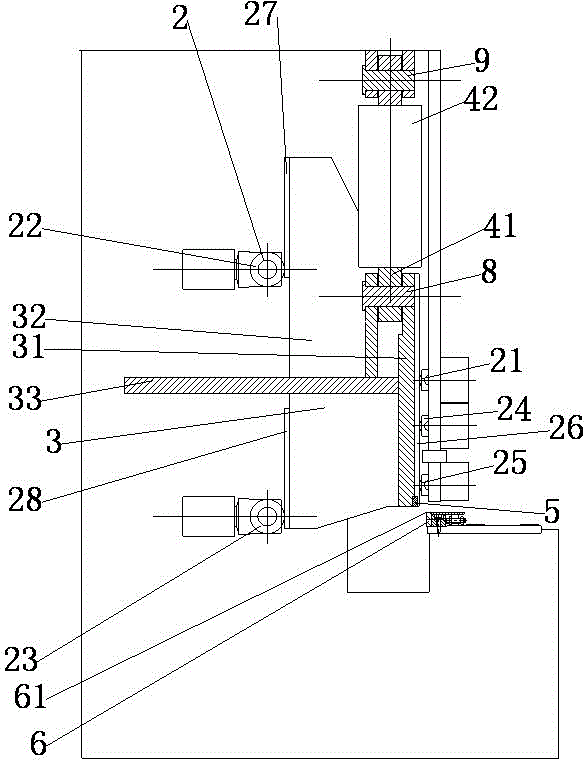
[0030] see image 3 , 4 The gate-type shearing machine of the present technology shown includes a frame 1, a knife rest 3 arranged on the frame through a three-point support structure 2 sliding up and down, and an oil cylinder 4 that drives the knife rest to move up and down.

[0031]Knife rest 3 comprises knife rest vertical plate 31, is fixed on the knife rest side plate 32 of knife rest both sides, is fixed on the knife rest horizontal plate 33 that extends horizontally along the knife rest vertical plate rear surface; The inclined shape of the low right side is high, the edge of the lower part of the knife rest vertical plate is fixed with the upper blade 5, and the lower blade 6 is fixed on the frame.

[0032] The three-point support structure 2 includes six fron...


PUM


Abstract

The invention provides a gate type plate shearing machine which is provided with front supporting points of a small structure and has a simple overall structure and low cost. The gate type plate shearing machine comprises a machine frame, a tool rest and an oil cylinder, wherein the tool rest is arranged on the machine frame through a three-point supporting structure in a vertical sliding mode, and the oil cylinder drives the tool rest to move vertically. The tool rest comprises a tool rest vertical plate and tool rest side plates fixed to the two sides of the tool rest. An upper blade is fixed to the lower edge of the oblique tool rest vertical plate, and a lower blade is fixed to the machine frame. The three-point supporting structure comprises the front supporting points, upper rear supporting points and lower rear supporting points, and the front supporting points, the upper rear supporting points and the lower rear supporting points are arranged on the machine frame. The front supporting points are elastic supporting points tightly pressed on the front of the tool rest, and the upper portion and the rear portion of the rear of the tool rest maintain contact with the upper rear supporting points and the lower rear supporting points respectively under the action of the elastic supporting points on the tool rest. The positions, in the vertical direction, of the lower rear supporting points are flush with the cutting edge of the lower blade.

Description

technical field [0001] The technology relates to a gate-type shearing machine for shearing metal sheets in the sheet metal forging industry. Background technique [0002] see figure 1 , 2 The existing gate-type shearing machine shown includes a frame 1, a knife rest 3 that slides up and down on the frame through a three-point support structure 2, and an oil cylinder 4 that drives the knife rest to move up and down. [0003] Knife rest 3 comprises knife rest vertical plate 31, is fixed on the knife rest side plate 32 of knife rest both sides, is fixed on the knife rest horizontal plate 33 that extends horizontally along the knife rest vertical plate rear surface; The inclined shape of the low right side is high, the edge of the lower part of the knife rest vertical plate is fixed with the upper blade 5, and the lower blade 6 is fixed on the frame. [0004] The three-point support structure 2 includes a front fulcrum 21 , a rear upper fulcrum 22 , and a rear lower fulcrum 2...

Claims


Application Information

Patent Timeline
Patent Type & Authority Applications(China)
IPC IPC(8): B23D15/08B23D15/14B23D33/00
Inventor 王军
Owner NANJING SHENGDA HEAVY IND MACHINERY
Why Eureka
Try Eureka