An electrical switchgear using pneumatically opened and closed sliding doors

An electrical switch and sliding door technology, applied in the field of electrical switch cabinets, can solve problems such as difficulty in ensuring airtight performance, and achieve the effects of reliable operation and simple structure

Inactive Publication Date: 2016-06-01
STATE GRID CORP OF CHINA +1
View PDF5 Cites 0 Cited by
  • Summary
  • Abstract
  • Description
  • Claims
  • Application Information

AI Technical Summary

Problems solved by technology

However, under frequent switching, it is difficult to guarantee this kind of airtight performance, and it is even more difficult to realize it under operation control

Method used


Image

  • An electrical switchgear using pneumatically opened and closed sliding doors
  • An electrical switchgear using pneumatically opened and closed sliding doors
  • An electrical switchgear using pneumatically opened and closed sliding doors

Examples


Embodiment Construction

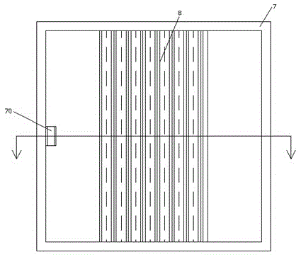
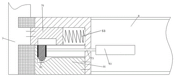
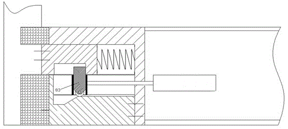
[0011] Combine below Figure 1-5 The present invention will be described in detail.

[0012] According to an embodiment, an electrical switch cabinet using a pneumatically opened and closed sliding door includes a cabinet body 7 and a sliding door 8 located at the front opening of the cabinet body 7, and the middle part of the frame of the cabinet body 7 is fixedly arranged toward the opening. There is a locking protrusion 70, and a dragging mechanism is provided at a side position of the sliding door 8 corresponding to the locking protrusion 70, and the dragging mechanism includes a mounting block 82 fixedly installed on the body of the sliding door 8 And the rail block 81 that is fixedly connected with the installation block 82, the rail block 81 forms a cavity together with the installation block 82, and the rail block 81 is provided with The right side includes the vertical blocking section 810 in the front and rear direction, the concave horizontal section 811, the trans...


PUM


Abstract

An electrical switch cabinet using a pneumatically opened and closed sliding door comprises a cabinet body (7) and a sliding door (8) disposed at the front opening of the cabinet body (7). A locking bump (70) is fixedly arranged in a position, facing the opening, in the middle of the frame of the cabinet body (7). A drag mechanism is arranged in a position of a side, corresponding to the locking bump (70), of the sliding door (8). The drag mechanism comprises an installation block (82) fixedly installed on the body of the sliding door (8) and a guide rail block (81) fixedly connected with the installation block (82). The guide rail block (81) and the installation block (82) form a cavity. The guide rail block (81) is provided with a contour part sequentially comprising a vertical blocking section (810), a concave horizontal section (811), a transitional slope section (812) and a convex horizontal section (813) in the front-rear direction from left to right on a side, facing the cavity, of the guide rail block (81).

Description

technical field [0001] The application relates to the field of electrical cabinets, in particular to an electrical switch cabinet using a pneumatically opened and closed sliding door. Background technique [0002] The operation door of the electrical switchgear needs to be opened and closed frequently to operate or maintain the electrical switches therein. Moreover, in some occasions, the electrical switchgear needs to have watertight airtight performance to ensure the normal and reliable operation of the internal electrical switching elements. However, under frequent switching, it is difficult to guarantee this airtight performance, and it is even more difficult to realize it under operation control. Contents of the invention [0003] The object of the present invention is to provide an electrical switchgear using a pneumatically opened and closed sliding door, which can overcome the above-mentioned defects of the prior art. [0004] According to the present invention, ...

Claims


Application Information

Patent Timeline
Patent Type & Authority Patents(China)
IPC IPC(8): H02B1/26
CPCH02B1/30
Inventor 吕尊堂衷新平石在朋梁修斌薛帅张瑞敏马腾韩兆峰狄东晗翟华江广冲刘志敬
Owner STATE GRID CORP OF CHINA
Why Eureka
Try Eureka