Methods for Optimizing Indoor Air Quality Equipment Placement and Indoor Environmental Quality

A technology of indoor air quality and placement position, applied in the field of optimizing indoor environment quality, can solve the problem that there is no basis for the placement of environmental quality sensors and air purification devices, the movement trajectory of indoor environment particles cannot be obtained, and it is impossible to optimize indoor environment quality. effects and other issues, to achieve optimal breathing health, good optimization effects, and avoid results errors.

Active Publication Date: 2018-12-07
SHENZHEN INST OF ADVANCED TECH
View PDF3 Cites 0 Cited by
  • Summary
  • Abstract
  • Description
  • Claims
  • Application Information

AI Technical Summary

Problems solved by technology

[0003] The purpose of the present invention is to provide a method for optimizing the placement of indoor air quality equipment, which aims to solve the problem of the lack of evidence for the placement of environmental quality sensors and air purification devices in the prior art due to the inability to obtain the movement trajectory of indoor environmental particles. to achieve a better indoor environment quality optimization effect

Method used


Image

  • Methods for Optimizing Indoor Air Quality Equipment Placement and Indoor Environmental Quality
  • Methods for Optimizing Indoor Air Quality Equipment Placement and Indoor Environmental Quality
  • Methods for Optimizing Indoor Air Quality Equipment Placement and Indoor Environmental Quality

Examples


Embodiment Construction

[0025] In order to make the technical problems, technical solutions and beneficial effects to be solved by the present invention clearer, the present invention will be further described in detail below in conjunction with the accompanying drawings and embodiments. It should be understood that the specific embodiments described here are only used to explain the present invention, not to limit the present invention.

[0026] An embodiment of the present invention provides a method for optimizing the placement of indoor air quality equipment, including the following steps:

[0027] S01. Establish an indoor three-dimensional model, and the indoor three-dimensional model is set according to the actual size and distribution of the research object;

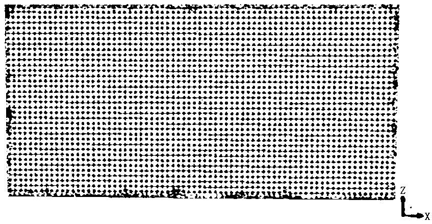
[0028] S02. After setting the boundary of the indoor three-dimensional model, performing grid division processing on the indoor three-dimensional model to obtain the gridded indoor three-dimensional model;

[0029] S03. Set the simulati...


PUM


Abstract

The invention is applicable to the field of environment quality monitoring and provides a method for optimizing a placement position of an indoor air quality device and a method for optimizing indoor environment quality. The method for optimizing the placement position of the indoor air quality device comprises the following steps of: establishing an indoor three-dimensional model, wherein the indoor three-dimensional model is set according to the actual size and distribution of a research object; performing boundary setting on the indoor three-dimensional model, and performing meshing on the indoor three-dimensional model, thereby obtaining a meshed indoor three-dimensional model; performing simulation boundary condition setting on meshes in the indoor three-dimensional model, and performing calculation to obtain a simulation result; and adding a discrete phase so as to perform simulation analysis on indoor movement loci of particles, and determining the placement position of the environment air quality device.

Description

technical field [0001] The invention belongs to the field of environmental quality monitoring, and in particular relates to a method for optimizing the placement position of indoor air quality equipment and a method for optimizing indoor environmental quality. Background technique [0002] With the development of the economy, people's quality of life is getting higher and higher, and indoor environmental quality detectors are becoming more and more popular. However, the accuracy of environmental quality detection has not been optimistic, especially in the monitoring of indoor particulate matter quality. Since most rooms are equipped with air-conditioning systems, the existence of air-conditioning changes the distribution of indoor particulate matter, which leads to environmental quality testing results. Particle detection is inaccurate. At present, the indoor environmental quality monitors sold in the market generally only detect the environmental quality of a fixed indoor ...

Claims


Application Information

Patent Timeline
Patent Type & Authority Patents(China)
IPC IPC(8): G06F17/50
Inventor 聂泽东王珍刘宇航李景振
Owner SHENZHEN INST OF ADVANCED TECH
Why Eureka
Try Eureka