Laser tool setting method for friction stir welding equipment

A welding equipment and friction stir technology, applied in welding equipment, non-electric welding equipment, metal processing equipment, etc., can solve the problems of reduced production efficiency, uneven precision, unstable mechanical properties of welds, etc., to improve tool setting efficiency , the effect of strength value improvement, high reliability

Active Publication Date: 2017-05-03
AEROSPACE ENG EQUIP SUZHOU CO LTD
View PDF6 Cites 0 Cited by
  • Summary
  • Abstract
  • Description
  • Claims
  • Application Information

AI Technical Summary

Problems solved by technology

[0003] (1) This step must be repeated before each welding, which increases the burden on the operator and reduces the production efficiency; (2) Since manual knife setting is judged by the naked eye, the same person at different angles and different orientations, The obtained tool setting accuracy is not the same, not to mention that when people with different experiences are engaged in tool setting, the accuracy is even more uneven, which seriously reduces the reliability of tool setting accuracy; (3) due to equipment, tooling and Due to the limitation of the workpiece on the operating space, sometimes the operator cannot perform effective tool setting, but the accuracy can be imagined after a rough judgment; (4) The mechanical properties of the weld are not stable

Method used


Image

  • Laser tool setting method for friction stir welding equipment

Examples


Embodiment Construction

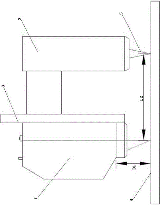
[0022] The present invention will now be further described in detail in conjunction with the accompanying drawings and embodiments. These drawings are all simplified schematic diagrams, only illustrating the basic structure of the present invention in a schematic manner, so it only shows the composition related to the present invention.

[0023] Tool calibration:

[0024] 1. A special stirring needle is installed on the spindle tool handle. The head of this special stirring needle is sharp and thin, which can effectively improve the precision of tool setting;

[0025] 2. Take any point on the weld as a calibration point, and mark it with a marker pen. Move the X / Y / Z axis (X axis—welding forward direction, Y axis—weld left and right direction, Z axis—weld height direction) through the hand-held unit of the welding equipment, so that the special stirring needle is aligned with the center of the standard weld point and Stick to the surface of the workpiece;

[0026] 3. Lift the...


PUM


Abstract

The invention relates to a laser tool setting method of friction-stir welding equipment. The laser tool setting method comprises the following steps: a stirring needle is installed on a tool handle of a main shaft; one point on the central line of a welding line is marked as a fixed point, and then a handhold unit is used for driving a moving mechanism, so that the end part of a stirring needle is tightly attached to the fixed point on the surface of a workpiece; the handhold unit is used for driving a Z shaft to be lifted by a preset distance, and then driving an X shaft to move by a position distance, so that laser beams emitted by a laser device passes through the fixed point to drive the Z shaft to descend by a preset distance; the laser beam is used for scanning to display the fixed point on a display device; the laser device is moved by an adjusting plate, so that a coordinate central point on a display and the fixed point displayed on the display device are overlapped; the stirring needle on the tool handle is replaced by a stirring head; the length difference value of the stirring head and the stirring needle on the Z shaft can be adjusted by the moving mechanism, so that the end part of the stirring head is tightly attached to the surface of the welding line, and the stirring head is at the starting position at the moment; the starting position is taken as a reference point, so that automatic tool setting is implemented by a software program.

Description

technical field [0001] The invention relates to a tool setting method, in particular to a laser tool setting method for friction stir welding equipment. Background technique [0002] In the friction stir welding process, usually before starting welding each time, the operator needs to fine-tune the Y-axis through the hand wheel to align the center of the stirring needle with the center of the weld, and fine-tune the Z-axis to make the tip of the stirring needle fit the surface of the welding workpiece, so as to set Determine the welding start point. This approach currently appears to have at least four disadvantages: [0003] (1) This step must be repeated before each welding, which increases the burden on the operator and reduces the production efficiency; (2) Since manual knife setting is judged by the naked eye, the same person at different angles and different orientations, The obtained tool setting accuracy is not the same, not to mention that when people with differe...

Claims


Application Information

Patent Timeline
Patent Type & Authority Patents(China)
IPC IPC(8): B23K20/12
CPCB23K20/124
Inventor 张晓进韦叶蔡智亮董肖节周法权杨国舜
Owner AEROSPACE ENG EQUIP SUZHOU CO LTD
Why Eureka
Try Eureka