A strip-shaped metal layer film punching device and method thereof

A metal layer and thin film technology, which is applied in the field of automatic punching devices for strip-shaped metal layer films, can solve the problems of damage to metal layer films, yields less than 80%, and low yields, and achieve the effect of reducing tensile damage

Active Publication Date: 2017-04-12
柔电芯云(珠海)科技有限公司
View PDF6 Cites 0 Cited by
  • Summary
  • Abstract
  • Description
  • Claims
  • Application Information

AI Technical Summary

Problems solved by technology

At least 4 steps are not suitable for industrial roll transfer (roll to roll)
This process requires 2 skilled workers to spend 2 days per group of patches (up to 6 pieces), and the yield is less than 80%.
This process is inefficient, expensive, has low yields, and is not suitable for industrial mass production
[0004] On the other hand, because the metal layer film is relatively thin and soft in texture, if the metal pattern product is produced by punching and shearing the inner circumference of the punch and the through hole in the existing stamping technology, it is easy to cut the metal layer between the punch and the through hole. When the film is cut, the impact pressure generated instantaneously causes the surface of the flexible film to stretch beyond its breaking tension, thereby destroying the metal layer film; while the traditional way of cutting the underlying material with a punch, the waste or film product being punched may be damaged during shearing. After cutting, it jumps out from the edge of the punch or is adsorbed on the punch, which cannot realize the production of the assembly line, and the surface of the processed metal layer film is prone to wrinkles, resulting in the scrapping of the plate

Method used


Image

  • A strip-shaped metal layer film punching device and method thereof
  • A strip-shaped metal layer film punching device and method thereof
  • A strip-shaped metal layer film punching device and method thereof

Examples


Embodiment Construction

[0034] The present invention will be described in further detail below through specific implementation examples and in conjunction with the accompanying drawings, but is not limited to these examples.

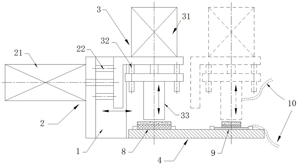
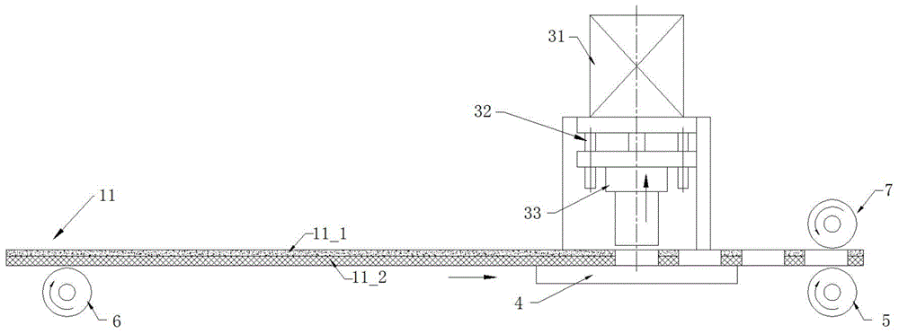
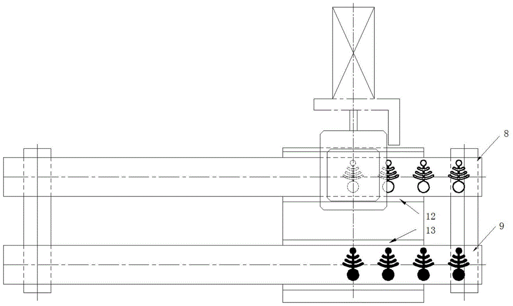
[0035] like figure 1 , 2 , shown in 3, a strip metal layer film punching device, including a base 1, a vacuum pump, a moving part 2, a stamping part 3, a vacuum hole supporting plate 4, a power wheel 5, a rotating wheel 6, a pressure wheel 7. Control unit.

[0036] The base 1 is placed on the ground or other supports, and is used to fix other main components of the band-shaped metal layer film die-cutting device, and plays a role of support and support for the entire device.

[0037] The vacuum pump pumps air through the connected vacuum tube 10 to the closed space inside the vacuum hole punch 33 and the vacuum hole supporting plate 4, thereby generating an adsorption force on the film contacted on the surface of the first adsorption hole 331_2.

[0038] The moving part 2 is...


PUM

PropertyMeasurementUnit
thicknessaaaaaaaaaa
thicknessaaaaaaaaaa
thicknessaaaaaaaaaa

Abstract

A belt metal layer film punching device. The device comprises a base (1), a vacuum pump, a moving component (2), a punching component (3), a vacuum hole supporting plate (4), a power wheel disc (5), a rotation wheel disc (6), and a pressure wheel disc (7). The punching component (3) comprises a punching power source (31), a punching guiding rod (32), and a vacuum hole male die (33). A cutting die (331_1) is disposed on the vacuum hole male die (33), and a first adsorption air-hole (331_2) is formed in the inner surface of a sealed region of the vacuum hole male die (33). The surface of the vacuum hole supporting plate (4) is provided with a female die (41_1), a positioning sliding groove (12, 13) and a second adsorption air-hole (41_2). Also disclosed is a belt metal layer film punching method. The method comprises: punching a belt metal layer film (11) by using a vacuum hole male die (33); adsorbing a cut metal pattern product on the surface of a vacuum hole male die (33), and adsorbing a punched waste material by suing a vacuum hole supporting plate (4); and sticking the product onto a new film by means of adsorptive transfer. Adsorptive control and transfer are performed on a cut metal pattern product by using the punching device, and it can be ensured that the cut product is prevented from jumping out of a punch, so that the production operation of an assembly line is implemented, and the flatness of the product surface is ensured.

Description

technical field [0001] The invention relates to a metal punching device and a method thereof, in particular to an automatic punching device for a band-shaped metal layer film and a method for punching a band-shaped metal layer film to form a metal pattern product by using the device. Background technique [0002] Metal is a non-elastic material. Under normal circumstances, the stretching of ordinary metals will cause fracture or other permanent deformation, and in the ultra-thin state of the metal (the thickness of the metal layer is between 20nm-200nm) and in a serpentine configuration In this case, the metal itself can be stretched and can return to its original state after stretching, but the metal of this thickness is very fragile and easy to break. By using the film as the supporting material of the metal, the metal in the Stable at this thickness. At the same time, through the preparation process, the metal film can be made into various required patterns, which can be...

Claims


Application Information

Patent Timeline
Patent Type & Authority Patents(China)
IPC IPC(8): B21D28/02B21D28/20B21D45/00
CPCB21D28/02B21D28/20B21D45/00
Inventor 杨泽宇
Owner 柔电芯云(珠海)科技有限公司
Why Eureka
Try Eureka