Telescope image derotator apparatus and collimation adjustment method thereof

A telescope and rotator technology, applied in telescopes, instruments, optics, etc., to achieve the effects of easy manufacturing, convenient installation and simple structure

Active Publication Date: 2016-03-23
CHANGCHUN INST OF OPTICS FINE MECHANICS & PHYSICS CHINESE ACAD OF SCI
View PDF4 Cites 13 Cited by
  • Summary
  • Abstract
  • Description
  • Claims
  • Application Information

AI Technical Summary

Problems solved by technology

[0004] In order to solve the problem of tracking the rotation of the field of view of the image square of the telescope, the invention provides a telescope image elimina

Method used


Image

  • Telescope image derotator apparatus and collimation adjustment method thereof
  • Telescope image derotator apparatus and collimation adjustment method thereof
  • Telescope image derotator apparatus and collimation adjustment method thereof

Examples


Embodiment Construction

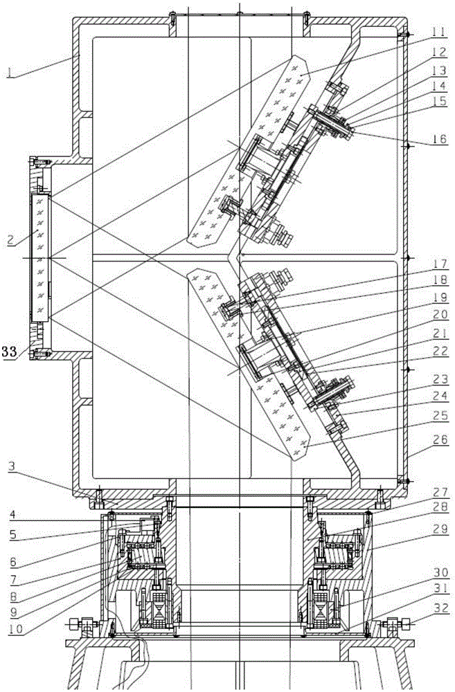
[0052] The present invention will be described in further detail below in conjunction with the accompanying drawings.

[0053] Such as figure 1 As shown, the telescope image elimination rotator device of the present invention mainly includes a casing 1, a reflector 2, a fixed plate 33, a connecting plate 3, a first inclined reflector 11, a second inclined reflector 25, and a casing cover plate 26 , Two sets of tilting mirror adjustment components, two sets of tilting mirror components, precision turntable components. The inside of the box body 1 is provided with an interface for installing the tilting mirror adjustment assembly and the tilting mirror assembly, the mirror 2 is fixed on the inner side wall of the box body 1 through the fixing plate 33, and the outer lower end of the box body 1 is connected to the precision turntable through the connecting plate 3 The components are fixedly connected, and after the installation and commissioning of the tilting mirror adjustment ...


PUM


Abstract

The invention provides a telescope image derotator apparatus and a collimation adjustment method thereof, and relates to the field of image derotator, being able to solve the problem for tracking rotation of image space field for a telescope. The telescope image derotator apparatus comprises a box body, a reflector, a fixed plate, a connection board, two steering mirrors, a box body cover plate, two sets of steering mirror adjusting assemblies for adjusting the steering mirrors, two sets of steering mirror assemblies for mounting the steering mirrors, and a precision rotary table assembly. The internal of the box body is provided with an interface for mounting the steering mirror adjusting assemblies and the steering mirror assemblies; the reflector is fixed on the side wall in the box body through the fixed plate; the lower end of the box body is fixedly connected with the precision rotary table assembly through the connection board; after mounting of the steering mirror adjusting assemblies and the steering mirror assemblies, the steering mirror adjusting assemblies and the steering mirror assemblies are sealed and protected by the box body cover plate; and the box body cover plate is fixed on the side wall outside of the box body through screws. The telescope image derotator apparatus has the advantages of being simple in structure, being low in processing and manufacturing difficulty, and being convenient to mount. The collimation adjustment method for the telescope image derotator apparatus is concise in operation and high in efficiency.

Description

technical field [0001] The invention relates to the technical field of image derotation, in particular to a telescope de-rotator device and a collimation installation and adjustment method thereof. Background technique [0002] When the telescope is tracking the target, due to the rotation of the pitch axis and the azimuth axis, the target image at the exit pupil rotates relative to the real situation. Even if the attitude of the target does not change, the captured image of the target rotates with the rotation of the telescope's pitch axis and azimuth axis, which brings inconvenience to real-time target recognition and image processing algorithms based on multi-frame accumulation. [0003] In order to obtain stable and high-quality images, the telescope needs to compensate for the rotation of the field of view. Generally, the electronic derotation method is adopted: by processing the image video signal collected in real time, after the rotation processing according to the ...

Claims


Application Information

Patent Timeline
IPC IPC(8): G02B23/10G02B23/12G02B23/16
CPCG02B23/10G02B23/12G02B23/16
Inventor 张岩张景旭陈宝刚
Owner CHANGCHUN INST OF OPTICS FINE MECHANICS & PHYSICS CHINESE ACAD OF SCI
Why Eureka
Try Eureka