Method and apparatus for localizing target sound source

A sound source and target technology, applied in the field of locating the target sound source, can solve the problems of not being able to judge whether the sound comes from the front or the rear, and the discrimination effect of multiple sound sources is difficult to satisfy, and achieve the effect of improving the resolution effect

Active Publication Date: 2016-04-06
BAIDU ONLINE NETWORK TECH (BEIJIBG) CO LTD
View PDF6 Cites 37 Cited by
  • Summary
  • Abstract
  • Description
  • Claims
  • Application Information

AI Technical Summary

Problems solved by technology

Because the dual microphones are not as delicate as the structure of the human ear, the sound source localization of the dual microphones has great limitations. For example, a plane composed of two microphones can only judge the sound range of 180 degrees in the space surrounding the microphone plane, and cannot judge the sound. Whether it is coming from the front or the rear, and it is difficult to distinguish multiple sound sources at the same time.

Method used


Image

  • Method and apparatus for localizing target sound source
  • Method and apparatus for localizing target sound source
  • Method and apparatus for localizing target sound source

Examples


Embodiment 1

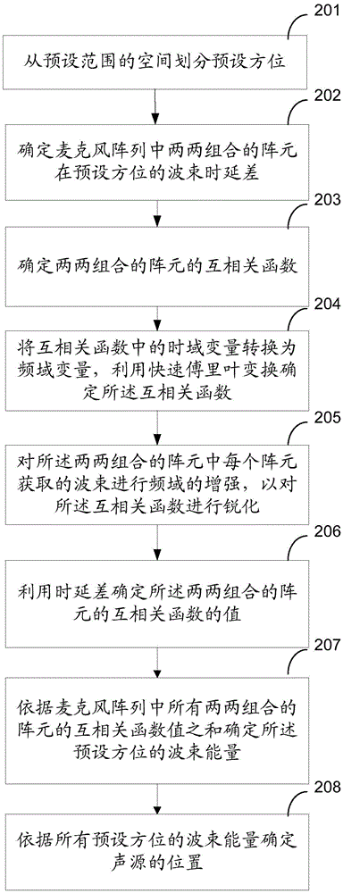
[0060] figure 2 It is a flowchart of a method for locating a target sound source provided by Embodiment 1 of the present invention. Such as figure 2 As shown, the method may include the following steps:

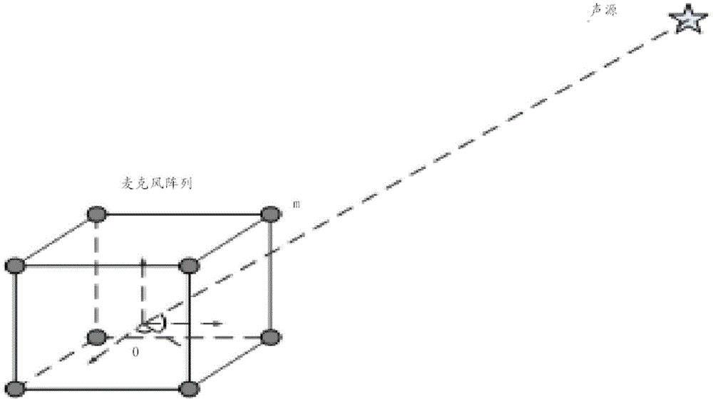
[0061] 201. Divide the space in the preset range into multiple preset orientations.

[0062] Specifically, when using the beam energy to determine the orientation of the target sound source, it is necessary to traverse all orientations within a 360-degree range around the microphone array, and then determine the position of the sound source according to the beam energy of all orientations. However, it takes a huge amount of calculation to calculate the beam energy in all directions, which is not necessary in actual use.

[0063] For example, for robots and other specific devices that need to locate sound sources, the positioning accuracy of about 5 degrees can meet the needs of daily life. Therefore, in order to improve computing efficiency, the preset range represented by...

specific example

[0127] Step 1: traverse all preset orientations (α, β), and find the corresponding delay difference between all microphone combinations in this orientation

[0128] Step 2: Combining formulas (2)-(4) to find the beam energy E in all directions (α,β) ;

[0129] Step 3: Set an energy threshold E MIN , the search beam energy E (α,β) The maximum value of E (α,β)Max , if E (α,β)Max greater than E MIN , then its corresponding orientation is the direction of the sound source;

[0130] Step 4: Combining formula (4), the existing sound source orientation (α, β) E_MAX Corresponding cross-correlation value set to 0;

[0131] Step 5: Repeat steps 2-4 to search for all possible sound source directions.

Embodiment 2

[0133] Figure 4 It is a schematic structural diagram of an apparatus for locating a target sound source provided by Embodiment 2 of the present invention. Such as Figure 4 As shown, the device may include the following units:

[0134] The preset orientation division unit 401 is configured to divide a preset range of space into multiple preset orientations.

[0135] Specifically, when using beam energy to determine the azimuth of a target sound source, it is necessary to traverse all azimuths within a 360-degree range around the microphone array, and then determine the location of the sound source according to the beam energy of all azimuths. However, it takes a huge amount of calculation to calculate the beam energy in all directions, which is not necessary in actual use.

[0136] Therefore, in order to improve calculation efficiency, the preset range represented by the space sphere around the microphone array can be divided into specific grids according to the needs of u...


PUM


Abstract

The invention discloses a method and apparatus for localizing a target sound source. The method comprises: wave beam delay differences of array elements at preset orientations in a microphone array are determined, wherein each two array elements are combined; on the basis of the delay differences, the sums of wave beam energy obtained by the array elements in a paired combination mode at the preset orientations are used as the wave beam energy of the preset orientations; and according to the wave beam energy of the preset orientations, location of a sound source is determined. According to the invention, with the microphone array, the location of the sound source is determined based on the wave beam energy of the microphone array at the preset orientations, thereby improving the resolution effect of the sound source.

Description

【Technical field】 [0001] The invention relates to sound processing technology, in particular to a method and device for locating a target sound source. 【Background technique】 [0002] The existing method of sound source localization is generally realized by using a microphone array. [0003] For dual-microphone sound source localization, it is simulated that human beings judge the position of the sound source by the time delay or phase difference between the arrival of the sound between the ears, so as to realize the sound source localization based on the anthropomorphic dual microphones. Because the dual microphones are not as delicate as the structure of the human ear, the sound source localization of the dual microphones has great limitations. For example, a plane composed of two microphones can only judge the sound range of 180 degrees in the space surrounding the microphone plane, and cannot judge the sound. Whether it is coming from the front or the rear, and the effe...

Claims


Application Information

Patent Timeline
Patent Type & Authority Applications(China)
IPC IPC(8): G01S5/22
CPCG01S5/22
Inventor 李峥李江勇戴腾
Owner BAIDU ONLINE NETWORK TECH (BEIJIBG) CO LTD
Why Eureka
Try Eureka