Biogas circulation desulfurization system

A desulfurization system and biogas technology, applied in the field of biogas cycle desulfurization system, can solve the problems of low desulfurization efficiency of biogas, low utilization rate of desulfurization agent, high production cost, etc., and achieve the effect of simple structure, high utilization rate and convenient operation

Inactive Publication Date: 2016-09-14
公安县前锋科技能源有限公司
View PDF3 Cites 0 Cited by
  • Summary
  • Abstract
  • Description
  • Claims
  • Application Information

AI Technical Summary

Problems solved by technology

[0003] The technical problem to be solved by the present invention is to provide a biogas cycle desulfurization system, which effectively solves the problem that the prior art biogas desulfurization equipment has a low utilizat

Method used


Image

  • Biogas circulation desulfurization system

Examples


Embodiment 1

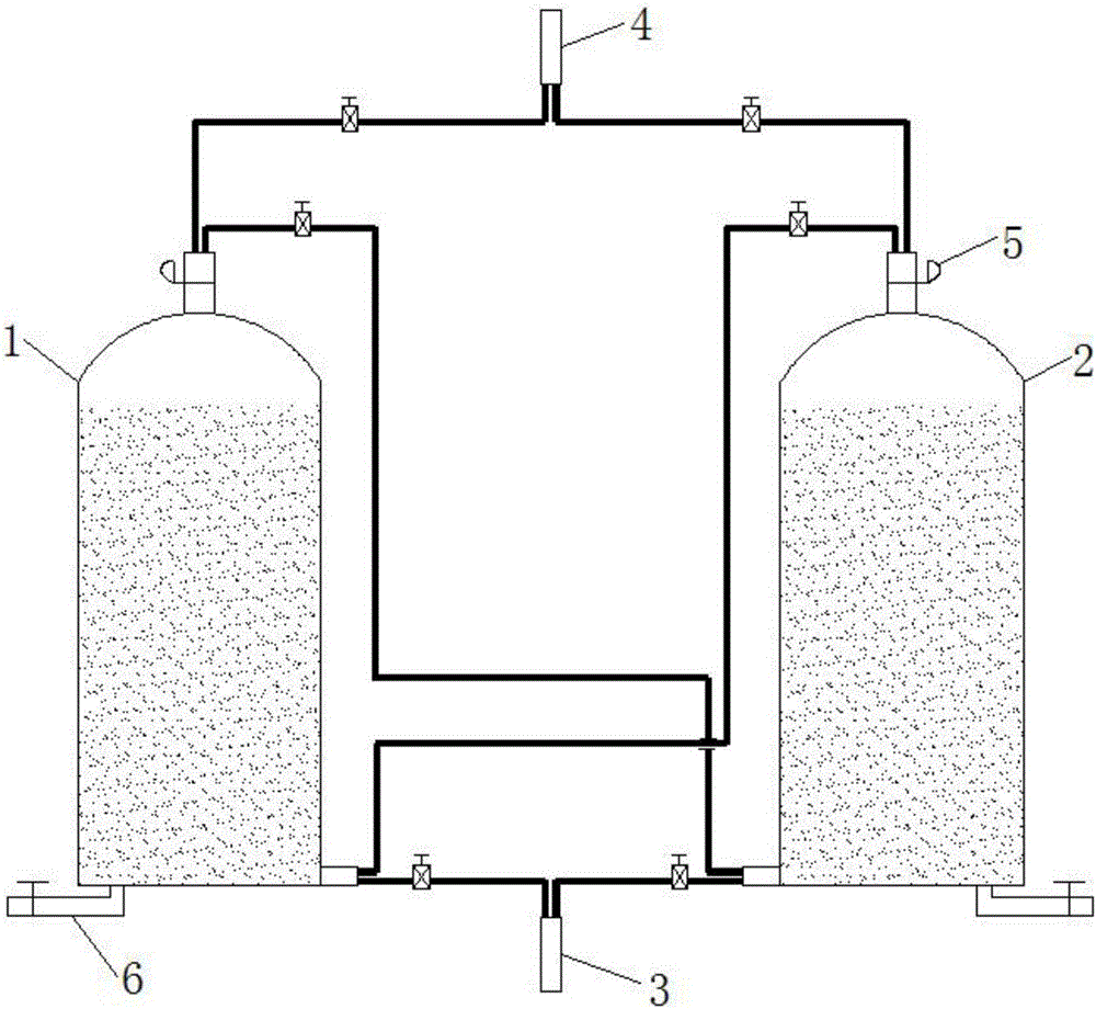
[0023] Embodiment one: if figure 1 As shown, the biogas circulation desulfurization system of this embodiment includes a first desulfurization tower 1 and a second desulfurization tower 2, the lower end side walls of the first desulfurization tower 1 and the second desulfurization tower 2 are provided with air inlets, and the top Gas outlets are all provided, and the air inlet of the first desulfurization tower 1 is connected to the gas outlet of the second desulfurization tower 2 through a pipeline, and the gas outlet of the first desulfurization tower 1 is connected to the air inlet of the second desulfurization tower 2 through a pipeline. The first desulfurization tower 1 and the second desulfurization tower 2 are respectively filled with desulfurizers.

[0024] It also includes a biogas intake main pipe 3, the air inlets of the first desulfurization tower 1 and the second desulfurization tower 2 are respectively connected to the biogas intake main pipe 3 through pipes, and...

Embodiment 3

[0032] Embodiment 3: Use the first desulfurization tower 1 and the second desulfurization tower 2 to desulfurize the biogas efficiently. solenoid valve, and close the solenoid valve on the pipeline between the gas inlet of the first desulfurization tower 1 and the gas outlet of the second desulfurization tower 2, so that the biogas that passes into the biogas inlet main pipe 3 is diverted and then introduced into the first desulfurization tower 1 and the gas outlet of the second desulfurization tower respectively. Desulfurization treatment is carried out in the second desulfurization tower 2 respectively. After the treatment, the gas outlets of the two are respectively converged into the biogas outlet main pipe 4 through pipelines, and then discharged in a concentrated manner and introduced into the subsequent packaging system.

[0033] When the biogas desulfurization process is carried out in the first desulfurization tower 1 or the second desulfurization tower 2, the moisture...


PUM


Abstract

The invention relates to the technical field of biogas desulfurization, and especially relates to a biogas circulation desulfurization system. The biogas circulation desulfurization system comprises a first desulfurization tower and a second desulfurization tower. The lateral walls of the lower ends of the first desulfurization tower and the second desulfurization tower are both provided with a gas inlet. The tops of the first desulfurization tower and the second desulfurization tower are both provided with a gas outlet. The gas inlet of the first desulfurization tower is communicated with the gas outlet of the second desulfurization tower through a pipeline, the gas outlet of the first desulfurization tower is communicated with the gas inlet of the second desulfurization tower through a pipeline; and the first desulfurization tower and the second desulfurization tower are filled with a desulfurizer. The biogas circulation desulfurization system has the advantages that the structure is simple, the operation and using are convenient, biogas can be fully circulated and desulfurized in the desulfurization towers, the sulfur content of desulfurized biogas is low, the utilization rate of desulfurizer is high, the desulfurization cost is saved, and the raw material loss is reduced.

Description

technical field [0001] The invention relates to the technical field of biogas desulfurization, in particular to a biogas circulation desulfurization system. Background technique [0002] At present, when desulfurizing biogas desulfurization, most of the biogas is passed into a single or multiple desulfurization towers for oxidative desulfurization. After a certain period of desulfurization, the content of the active components of the desulfurizer inside the tower gradually decreases. As a result, the biogas passing into the tower body cannot be fully desulfurized, and the sulfur content in the biogas coming out of the gas outlet of the tower body cannot meet the actual demand. At this time, the desulfurizer in the tower body must be replaced and refilled. , which makes the utilization rate of the desulfurization agent in the tower lower, and causes a lot of waste of desulfurization agent. At the same time, frequent replacement of desulfurization agent makes the desulfurizati...

Claims


Application Information

Patent Timeline
IPC IPC(8): C10L3/10
CPCC10L3/103
Inventor 吴松林
Owner 公安县前锋科技能源有限公司
Why Eureka
Try Eureka