Device for detecting working state of electromagnetic valve

A detection device and working state technology, applied in the direction of using electric/magnetic devices to transmit sensing components, etc., can solve the problems of inaccurate detection of working state, lack of safety protection, etc., and achieve the effect of accurate detection and convenient use

Active Publication Date: 2016-11-23
HEBEI QINHAN ELECTRONICS TECH CO LTD
View PDF6 Cites 6 Cited by
  • Summary
  • Abstract
  • Description
  • Claims
  • Application Information

AI Technical Summary

Problems solved by technology

[0006] The technical problem mainly solved by the present invention is to provide a detection device for the working state of the solenoid valve, so as to solve the problems of inaccurate detection of the working state of the solenoid valve working on-line and lack of safety protection in the prior art.

Method used


Image

  • Device for detecting working state of electromagnetic valve
  • Device for detecting working state of electromagnetic valve
  • Device for detecting working state of electromagnetic valve

Examples


Embodiment Construction

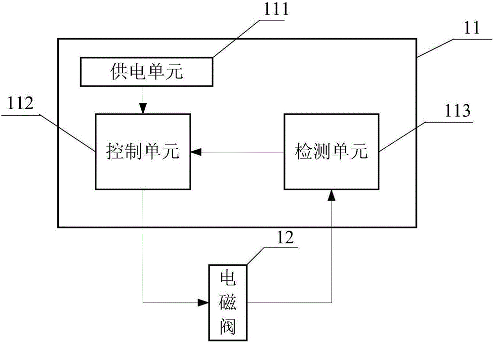
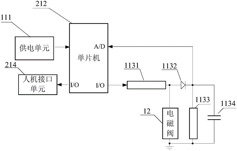
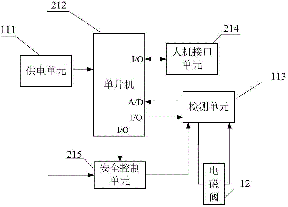
[0027] In order to facilitate the understanding of the present invention, the present invention will be described in more detail below in conjunction with the accompanying drawings and specific embodiments. Preferred embodiments of the invention are shown in the accompanying drawings. However, the present invention can be implemented in many different forms and is not limited to the embodiments described in this specification. On the contrary, these embodiments are provided to make the understanding of the disclosure of the present invention more thorough and comprehensive.

[0028] It should be noted that, unless otherwise defined, all technical and scientific terms used in this specification have the same meaning as commonly understood by those skilled in the technical field of the present invention. Terms used in the description of the present invention are only for the purpose of describing specific embodiments, and are not used to limit the present invention. The term "...


PUM


Abstract

The invention discloses a device for detecting a working state of an electromagnetic valve. By arranging a single chip microcomputer and a detection unit in the device, the single chip microcomputer inputs alternating current with a fixed frequency into a to-be-detected electromagnetic valve, the detection unit detects voltage signals at two ends of the electromagnetic valve working online in real time and returns and inputs the voltage signals to the single chip microcomputer, and therefore, the working state of the electromagnetic valve is judged. A human-machine interface unit and a safe control unit are further arranged in the device and are respectively used for setting operations, displaying states and guaranteeing the safe closing of the electromagnetic valve. The device is used for detecting whether the electromagnetic valve is in an on or off state according to the change of an inductance value of the electromagnetic valve in an on or off state, inductance represents different reactances under alternating current, and the on or off state of the electromagnetic valve can be judged by analyzing the change of the voltage by virtue of a resistive subdivision principle, and accurate detection of the working state of the electromagnetic valve is realized.

Description

technical field [0001] The invention relates to a detection device, in particular to a detection device for the working state of an electromagnetic valve. Background technique [0002] Solenoid valve is an electronically controlled valve switch, which usually includes an electromagnet wound with a coil. When power is applied to both ends of the coil, the electromagnet generates electromagnetic force to lift the center moving component from the valve seat, and the valve opens; when the power is turned off, The electromagnetic force disappears, and the spring presses the center moving assembly on the valve seat again, and the valve closes. The working state of the solenoid valve mainly refers to the on and off state of the solenoid valve. [0003] In practical applications, real-time online detection of the working status of the solenoid valve is required. This detection cannot affect the normal operation of the solenoid valve. At the same time, this real-time detection must ...

Claims


Application Information

Patent Timeline
Patent Type & Authority Applications(China)
IPC IPC(8): G01D5/20
CPCG01D5/20
Inventor 刘忠华翁征华熊明
Owner HEBEI QINHAN ELECTRONICS TECH CO LTD
Why Eureka
Try Eureka