liquid suction device

A suction device, liquid technology, applied in vacuum cleaners, manual floor scrubbing machinery, carpet cleaning, etc., can solve problems such as low-intensity negative pressure

Active Publication Date: 2020-04-21
VORWERK & CO INTERHOLDING GMBH
View PDF6 Cites 0 Cited by
  • Summary
  • Abstract
  • Description
  • Claims
  • Application Information

AI Technical Summary

Problems solved by technology

[0003] The disadvantage of this liquid suction device is that the suction head leaves liquid marks on the surface to be cleaned, especially in the area of ​​the gap end of the suction slot, because it is in contact with the center of the slot of the suction slot, which is close to the suction channel. than, the area at the end of the gap is applied with a lower intensity of negative pressure

Method used


Image

  • liquid suction device
  • liquid suction device

Examples


Embodiment Construction

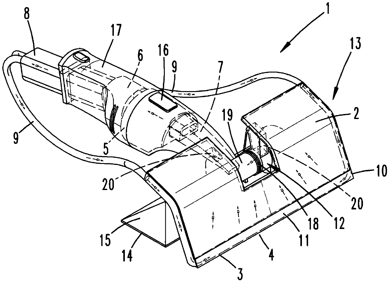
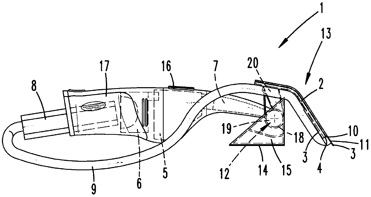
[0022] A wet cleaning device 13 is shown, designed here as a hand-held guided wet cleaning device, which has a liquid suction device 1 as well as a cleaning element 14 and a liquid application device 15 . The cleaning element 14 and the liquid application device 15 are designed as a common surface installation with a liquid reservoir. On the side facing the surface to be cleaned, the liquid tank has a cleaning element 14 , designed here as a cleaning cloth. The liquid application device 15 and the cleaning element 14 are connected to each other through the perforations of the wall of the liquid application device 15 in such a way that the liquid is continuously supplied from the storage tank of the liquid application device 15 to the cleaning element 14 and is thus applied to the surface to be cleaned. in the cleaning process.

[0023] The liquid suction device 1 of the wet cleaning device 13 has a suction head 2 which is designed here as a flat, double-walled part between wh...


PUM


Abstract

The present invention relates to a liquid suction device (1) with a suction head (2), a sewage storage tank (5) and a suction fan (6). The suction head (2) has a suction slot (4) defined by two lips (3), wherein the suction slot (4), the sewage storage tank (5) and the suction fan (6) are mutually connected to each other by means of suction passage (7), so that the liquid can be sucked from a surface to be cleaned to the sewage storage tank (5) through the suction slot (4). In order to provide the liquid suction device (1) which does not has liquid marks, it is suggested that an air passage (8) is arranged, and one side is connected to a pressure side of the fan, especially a pressure side of the suction fan (6) away from the suction passage (7), and the other side is connected to the suction slot (4), so that the blowing air from the fan, especially the suction fan (6) can be sent to the suction slot (4). Moreover the invention also relates to a wet cleaning device (13) with the liquid suction device (1), and a method for sucking the liquid from the surface to be cleaned by means of the liquid suction device (1).

Description

technical field [0001] The invention relates to a liquid suction device, in particular for suctioning liquids from hard floor surfaces and / or window surfaces, said liquid suction device having a suction head, a sewage storage tank and a suction fan, said suction The head has a suction slit delimited by two lips, wherein the suction slit, the sewage tank and the suction fan are interconnected by means of a suction channel so that liquid can pass through the suction slit from the surface to be cleaned is sucked into the sewage storage tank. Background technique [0002] Liquid suction devices of this type are known in the prior art. The liquid suction device is usually used in combination with cleaning elements in wet cleaning devices, which first apply liquid to the surface to be cleaned by means of a liquid application device, treat the surface by means of the cleaning element and then apply the liquid by means of the liquid suction device Excess liquid is sucked away from...

Claims


Application Information

Patent Timeline
Patent Type & Authority Patents(China)
IPC IPC(8): A47L7/00
CPCA47L7/0004A47L1/05A47L7/0009A47L11/29A47L11/34
Inventor J.舍费尔
Owner VORWERK & CO INTERHOLDING GMBH
Why Eureka
Try Eureka