Antenna device and mobile terminal with same

An antenna device and mobile terminal technology, applied in the field of antenna devices and mobile terminal equipment, can solve problems such as poor performance of multiplexed antennas, and achieve the effects of miniaturized compatible design, reduced resistance, and increased magnetic field strength

Active Publication Date: 2017-01-11
QINGDAO HISENSE MOBILE COMM TECH CO LTD
View PDF5 Cites 17 Cited by
  • Summary
  • Abstract
  • Description
  • Claims
  • Application Information

AI Technical Summary

Problems solved by technology

[0006] The purpose of the present invention is to provide an antenna device and a mobile terminal with the antenna device, so as to solve the problem of poor performance of multiplexed antennas in the prior art

Method used


Image

  • Antenna device and mobile terminal with same
  • Antenna device and mobile terminal with same
  • Antenna device and mobile terminal with same

Examples


no. 1 example

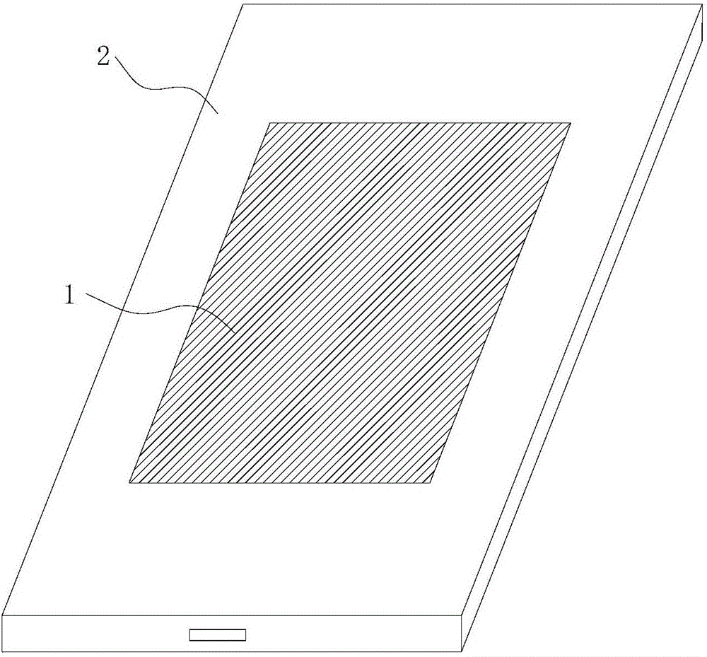
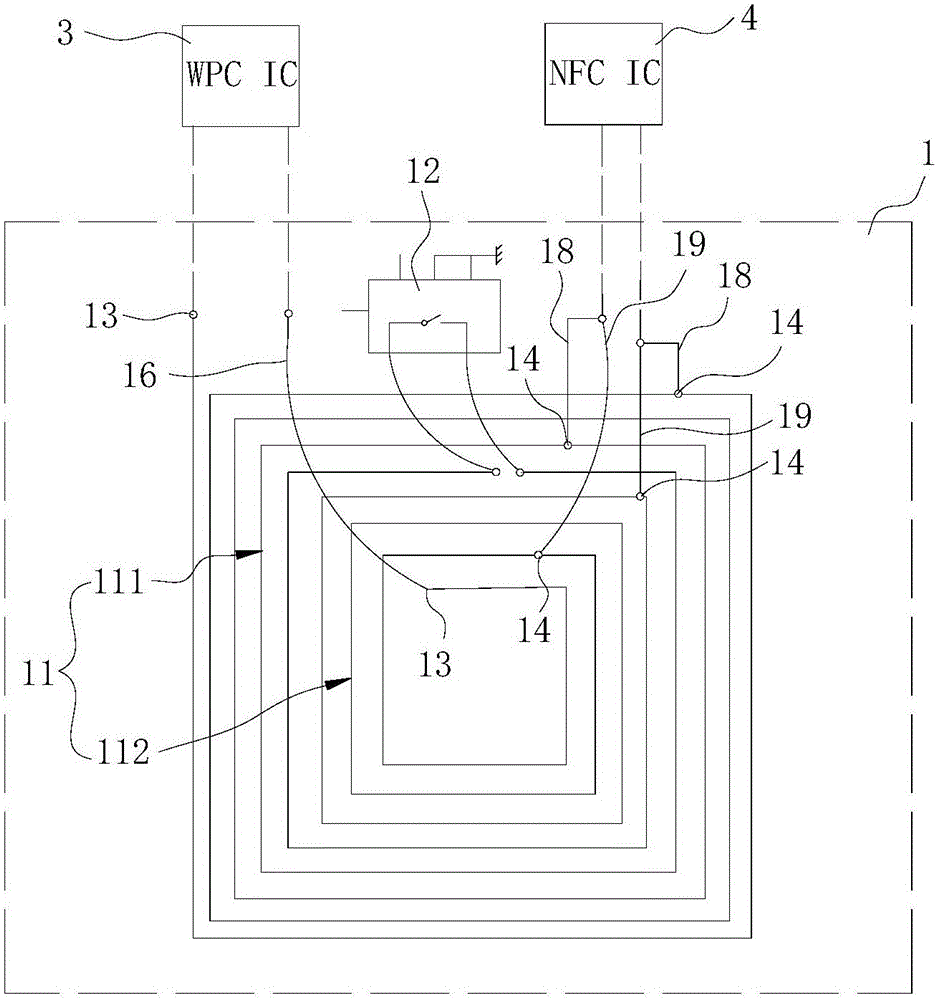
[0028] refer to figure 2 , as a typical application, the antenna device 1 in this embodiment realizes the multiplexing of the WPC function and the NFC function. Correspondingly, a WPC chip 3 and an NFC chip 4 need to be set in the mobile terminal to support the WPC function and the NFC function.

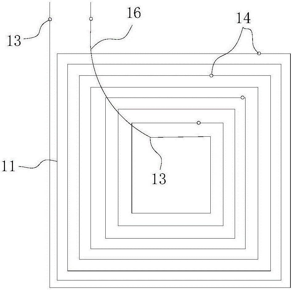
[0029] The antenna device 1 is designed in a single-sided routing mode. The main body of the antenna device 1 is a coil 11, and the coil 11 is a single-sided winding coil, and the coil 11 is routed in a rectangular spiral shape.

[0030] Both ends of the coil 11 are provided with a first feed point 13 for connecting to the WPC chip 3, wherein the first feed point 13 at the inner end of the coil 11 is drawn out through a jumper wire 16, and then electrically connected to the first feed point 13 at the outer end of the coil 11. It is connected to the input terminal and output terminal of the WPC chip 3 to form a WPC charging loop.

[0031] A switch unit 12 is provided on the coil 11...

no. 2 example

[0049] refer to Figure 6 and Figure 7 The difference between the antenna device of this embodiment and the antenna device of the first embodiment is that in this embodiment, the coil 11 is a double-layer wound coil, and the coil segments divided by the switch unit 12 are respectively arranged on the second coil 11. First and second floors. In order to distinguish it from the first embodiment, in this embodiment, the two coil segments are respectively called the first layer coil 11a and the second layer coil 11b.

[0050] The first-layer coil 11a and the second-layer coil 11b are stacked, and the projected areas of the two overlap.

[0051] The inner end point of the first layer coil 11a is connected to the inner end point of the second layer coil 11b through the switch unit 12, so that the two layer coils can be connected to each other or electrically isolated from each other.

[0052] The first layer coil 11a and the second layer coil 11b are respectively provided with a...

no. 3 example

[0063] The difference between the antenna device of this embodiment and the antenna device of the second embodiment is that in this embodiment, the respective outer terminals of the first layer coil 11a and the second layer coil 11b are connected through the switch unit 12, correspondingly, the two layers of coils are A first feeding point 13 is arranged close to each inner end point.

[0064] For other structures of this embodiment, refer to the second embodiment of the antenna device. The structure of the antenna device in this embodiment is omitted from illustration.


PUM


Abstract

The invention provides an antenna device and a mobile terminal with the same. The antenna device comprises at least two layers of stacked coils; a second feed point electrically connected to an NFC (Near Field Communication) chip or an RFID (Radio Frequency Identification) chip is respectively arranged on the coils, and a first feed point electrically connected to a WPC (Wireless Power Consortium) chip or an FM (Frequency Modulation) chip is respectively arranged on the two coils of the surface; and the two adjacent layers of coils are isolated by an isolating unit, and the isolating unit is configured to isolate working signals of the NFC chip or the RFID chip. The antenna device realizes superposition of effective area of antennas via multilayer superposed coils, the coils can be connected or isolated to support two different functions, and multiplexing of the antenna device is realized; meanwhile, in the NFC or RFID working mode, the intensity of the radiation electromagnetic field can be improved, and the NFC or RFID communication performance is optimized.

Description

technical field [0001] The invention relates to the field of mobile terminal equipment, in particular to an antenna device and a mobile terminal with the antenna device. Background technique [0002] With the continuous development of mobile terminal technology, the functions carried by the mobile terminal are no longer limited to communication. In recent years, related additional functions such as mobile payment and wireless charging have gradually become the standard configuration of mobile terminals and are sought after by consumers. The development trend of mobile terminals is to become the main carrier of human social activities, consumption and other activities, and its additional new functions have become one of its main selling points, and the compatible technology for functions has also become the research and development focus of relevant terminal design manufacturers. [0003] In current mobile terminals such as mobile phones, products compatible with NFC (Near F...

Claims


Application Information

Patent Timeline
Patent Type & Authority Applications(China)
IPC IPC(8): H01Q1/50H01Q1/24H01Q7/00H04M1/02
CPCH01Q1/242H01Q1/50H01Q7/00H04M1/0202
Inventor 宋成杰胡育根张波
Owner QINGDAO HISENSE MOBILE COMM TECH CO LTD
Why Eureka
Try Eureka