Antenna device and mobile terminal with the antenna device
An antenna device and mobile terminal technology, applied in the field of antenna devices and mobile terminal equipment, can solve problems such as poor performance of multiplexed antennas, and achieve the effects of miniaturized compatible design, reduced resistance, and increased magnetic field strength
- Summary
- Abstract
- Description
- Claims
- Application Information
AI Technical Summary
Problems solved by technology
Method used
Image
Examples
no. 1 example
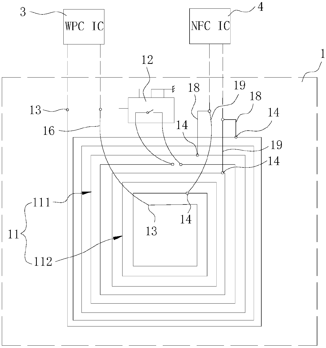
[0028] refer to figure 2 , as a typical application, the antenna device 1 in this embodiment realizes the multiplexing of the WPC function and the NFC function. Correspondingly, a WPC chip 3 and an NFC chip 4 need to be set in the mobile terminal to support the WPC function and the NFC function.
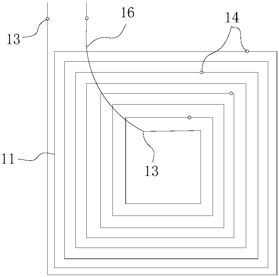
[0029] The antenna device 1 is designed in a single-sided routing mode. The main body of the antenna device 1 is a coil 11, and the coil 11 is a single-sided winding coil, and the coil 11 is routed in a rectangular spiral shape.
[0030] Both ends of the coil 11 are provided with a first feed point 13 for connecting to the WPC chip 3, wherein the first feed point 13 at the inner end of the coil 11 is drawn out through a jumper wire 16, and then electrically connected to the first feed point 13 at the outer end of the coil 11. It is connected to the input terminal and output terminal of the WPC chip 3 to form a WPC charging loop.
[0031] A switch unit 12 is provided on the coil 11...
no. 2 example
[0049] refer to Figure 6 and Figure 7 The difference between the antenna device of this embodiment and the antenna device of the first embodiment is that in this embodiment, the coil 11 is a double-layer wound coil, and the coil segments divided by the switch unit 12 are respectively arranged on the second coil 11. First and second floors. In order to distinguish it from the first embodiment, in this embodiment, the two coil segments are respectively called the first layer coil 11a and the second layer coil 11b.
[0050] The first-layer coil 11a and the second-layer coil 11b are stacked, and the projected areas of the two overlap.
[0051] The inner end point of the first layer coil 11a is connected to the inner end point of the second layer coil 11b through the switch unit 12, so that the two layer coils can be connected to each other or electrically isolated from each other.
[0052] The first layer coil 11a and the second layer coil 11b are respectively provided with a...
no. 3 example
[0063] The difference between the antenna device of this embodiment and the antenna device of the second embodiment is that in this embodiment, the respective outer terminals of the first layer coil 11a and the second layer coil 11b are connected through the switch unit 12, correspondingly, the two layers of coils are A first feeding point 13 is arranged close to each inner end point.
[0064] For other structures of this embodiment, refer to the second embodiment of the antenna device. The structure of the antenna device in this embodiment is omitted from illustration.
PUM
 Abstract
Description
Claims
Application Information
 - R&D
- Intellectual Property
- Life Sciences
- Materials
- Tech Scout
- Unparalleled Data Quality
- Higher Quality Content
- 60% Fewer Hallucinations
Browse by: Latest US Patents, China's latest patents, Technical Efficacy Thesaurus, Application Domain, Technology Topic, Popular Technical Reports.
© 2025 PatSnap. All rights reserved.Legal|Privacy policy|Modern Slavery Act Transparency Statement|Sitemap|About US| Contact US: help@patsnap.com


