Circulation storage cabinet

A technology of lockers and cabinets, which is applied in the field of circular lockers, can solve the problems of high labor intensity of the staff, hinder the appearance of the warehouse, and not suitable for the storage of precision spare parts, etc., so as to improve the efficiency of material management, facilitate the distinction and The effect of identification, convenient instant access

Inactive Publication Date: 2017-04-05
夏树伟
View PDF0 Cites 0 Cited by
  • Summary
  • Abstract
  • Description
  • Claims
  • Application Information

AI Technical Summary

Problems solved by technology

The main disadvantages of this management method are: the height and area of ​​the existing house cannot be fully utilized; it is necessary to frequently pick up the items placed on the upper shelf, use ladders to climb up and down, and carry them over long distances. The labor intensity of the staff is high and the efficiency is low. The items on the open shelves are polluted by dust and are not suitable for the storage of some precision spare parts; it is impossible to restrict irrelevant personnel from accessing items on the shelves, which makes the management chaotic; it is difficult to adopt the first-in first-out management method, inventory, clear The warehouse is difficult; the warehouse looks messy, untidy and beautiful, which hinders the appearance of the warehouse

Method used


Image

  • Circulation storage cabinet
  • Circulation storage cabinet
  • Circulation storage cabinet

Examples


Embodiment 1

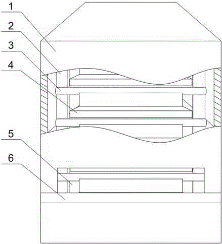
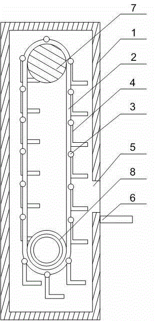
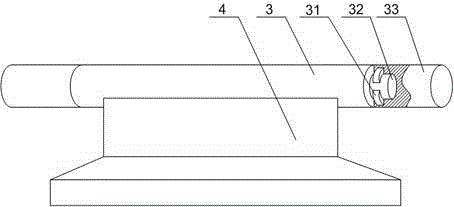
[0023] Such as Figure 1~Figure 5 As shown, the present embodiment includes a cabinet body 1, two motors and two groups of main sprocket 8 and driven sprocket 7 which are arranged on the inner wall of the cabinet body 1 for rotation, and the main sprocket 8 and driven sprocket 7 pass through the chain 2 Connection and cooperation, the output end of the motor is connected with the main sprocket 8, and the cabinet body 1 is provided with a delivery port 5, and also includes a plurality of rotating shafts 3, and the rotating shaft 3 is composed of a main body located in the middle section and fixed sections 33 at both ends. Composition, the hopper 4 is fixed on the main body, the fixed section 33 is embedded in the chain 2, and the movable cavity 34 with an elliptical cross section is arranged inside the fixed section 33, and the two ends of the main body are A narrowing section 32 is arranged on the outer extension, and two limiting blocks 31 whose thickness increases along the ...


PUM


Abstract

The invention discloses a circulation storage cabinet. The circulation storage cabinet comprises a cabinet body, two motors, drive chain wheels and driven chain wheels, and the drive chain wheels and the driven chain wheels are arranged in two sets. Each rotating shaft is composed of a body located in a middle section and fixing sections at the two ends, wherein a hopper is fixed to the body, a movable cavity with the oval cross section is formed in each fixing section, and shrinkage sections are arranged at the two ends of the body in an outward extending manner. Two limiting blocks with the thicknesses gradually increased in the circumference direction of each shrinkage section are symmetrically arranged on the outer wall of the shrinkage section along the axis of the shrinkage section. Inner annular teeth are arranged at the middle portions of the drive chain wheels, and multiple rotation teeth engaged with the inner annular teeth are fixed to the outer wall of a rotation barrel. When the biggest ends of the limiting blocks slide through the tail ends of half long shafts of the cross sections of the movable cavities, the biggest ends of the limiting blocks make contact with the walls of the movable cavities, then continuous rotation of the limiting blocks, the rotating shafts and the hoppers is stopped, and the situation that the swinging amplitude of the hoppers is continuously increased, and the hoppers collide with the adjacent or approaching hoppers is avoided.

Description

technical field [0001] The invention relates to logistics storage equipment, in particular to a circulation locker. Background technique [0002] Most enterprises basically adopt the traditional storage management method for the storage of spare parts - ordinary open shelf storage. The main disadvantages of this management method are: the height and area of ​​the existing house cannot be fully utilized; it is necessary to frequently pick up the items placed on the upper shelf, use ladders to climb up and down, and carry them over long distances. The labor intensity of the staff is high and the efficiency is low. The items on the open shelves are polluted by dust and are not suitable for the storage of some precision spare parts; it is impossible to restrict irrelevant personnel from accessing items on the shelves, which makes the management chaotic; it is difficult to adopt the first-in first-out management method, inventory, clear The warehouse is difficult; the warehouse ...

Claims


Application Information

Patent Timeline
Patent Type & Authority Applications(China)
IPC IPC(8): B65G1/137
Inventor 夏树伟
Owner 夏树伟
Why Eureka
Try Eureka