Al technical title is built by PatSnap Al team. It summarizes the technical point description of the patent document.
A stapler and foreskin technology, applied in the field of foreskin staplers, can solve the problems of being unable to observe and grasp the progress of cutting and stapling, too much or too little cutting of the frenulum, and the effect of nail removal is not good enough, so as to improve the comfort of surgery degree, reduce bleeding, and facilitate the effect of cutting
Active Publication Date: 2017-05-31
吴健强
View PDF8 Cites 2 Cited by
Summary
Abstract
Description
Claims
Application Information
AI Technical Summary
This helps you quickly interpret patents by identifying the three key elements:
Problems solved by technology
Method used
Benefits of technology
Problems solved by technology
[0004] Yet this circumcision device has following shortcoming: 1. blade is assembled, and operation quality is affected by assembly precision, and human factor influence is big
2. Before cutting, there are no parts to pre-press and position the tissue elastically, and the knife is cut directly to make the tissue easy to shift during the cutting process
3. The push-type handle structure is used for cutting in the front and rear directions. The cutting action is large and it is easy to damage the tissue. The cutting process is a blind cut, and it is impossible to observe and grasp the progress of cutting and stapling. child
4. There is no structure for protecting the frenulum and quantitative resection. During the cutting process, the doctor can only rely on the doctor to tilt the stapler to protect the frenulum, which may cause too much or too little cutting of the frenulum.
5. Using ordinary nails with thinner nail beams, the effect of nail removal during tissue healing is not good enough
Method used
Image
Click on the blue label to locate the original text in one second.
Reading with bidirectional positioning of images and text.
Examples
Embodiment Construction
[0038] The present invention will be described in further detail below.
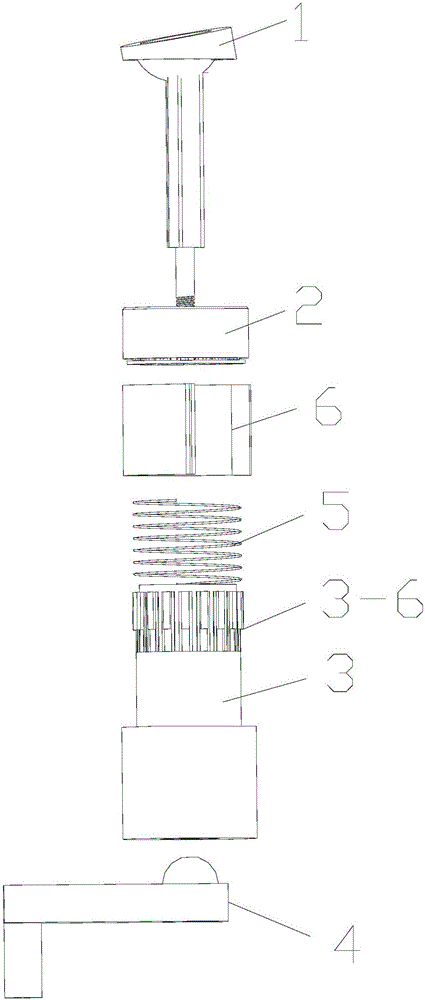
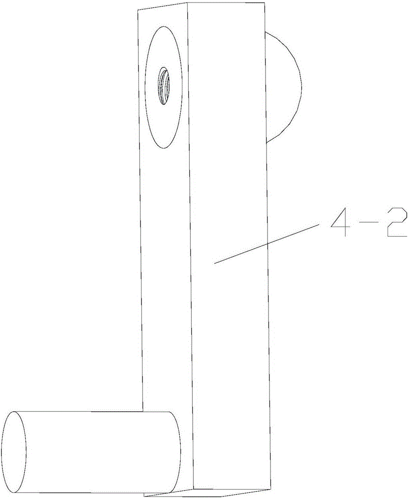
[0039] A prepuce stapler comprises a glans seat, a sliding nail bin, a body, a knife closing mechanism, a buffering and pressing mechanism, and a protection card.
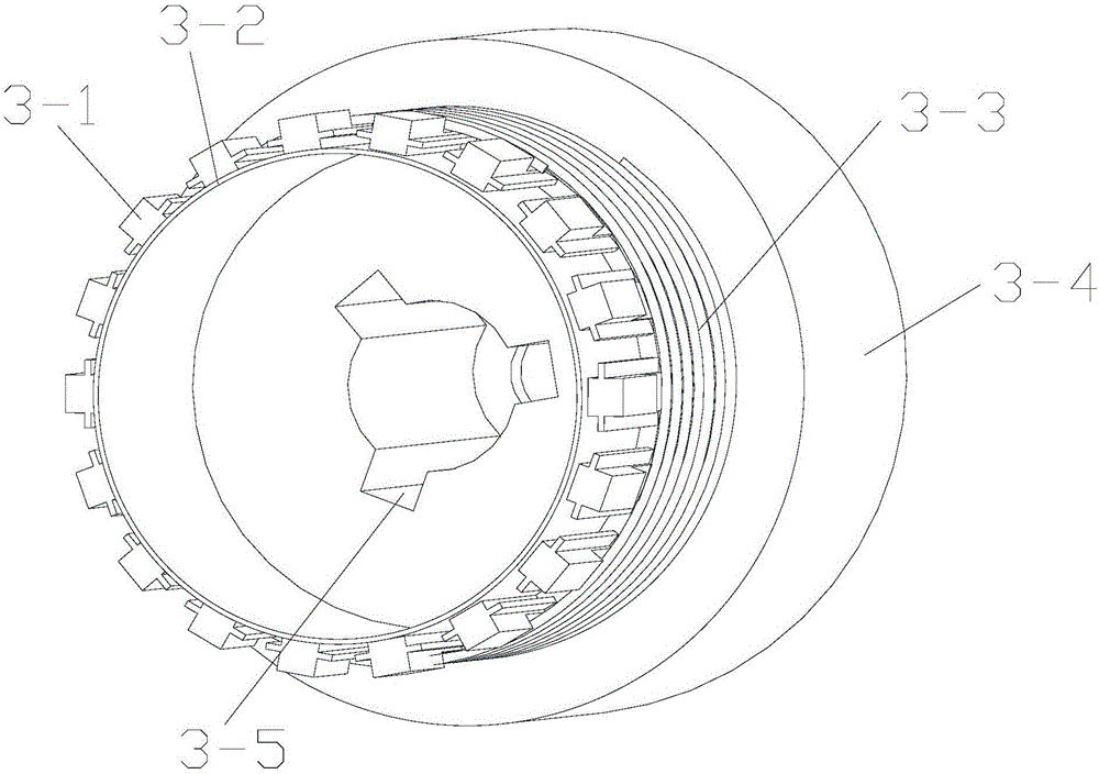
[0040] The main body is cylindrical as a whole, and the outer side is successively top nail piece, cushioning and pressing mechanism installation section, and platform stage with larger outer diameter from front to back. The top nail piece includes a plurality of top nail units distributed circularly and uniformly along the outer wall. The circular cutting knife is a stainless steel knife, and the front end slightly protrudes to the front of the top nail, so as to realize cutting and top nail at the same time. The annular cutter is fixed in the body through integral injection molding.
[0041] The sliding staple cartridge is in the shape of a cylinder as a whole, and there are multiple nail grooves evenly distributed along the ring on the i...
PUM
Abstract
The invention belongs to the technical field of surgical instruments and relates to a prepuce anastomat. The prepuce anastomat comprises a glans holder, a slide staple chamber, a body, a knife closing mechanism and a buffering compression mechanism. The body comprises a staple ejector and a circumcision knife, the staple ejector is positioned on the outer side of the front end of the body, and the circumcision knife is positioned on the inner side of the staple ejector and extends to the front of the staple ejector. The slide staple chamber with anastomosis staples mounted at the front end sleeves the staple ejector, and the buffering compression mechanism which pushes the slide staple chamber forwards is mounted between the slide staple chamber and the body. The glans holder for fixing tissues is provided with a knife abutting ring matched with the circumcision knife and staple anvils matched with the anastomosis staples in the slide staple chamber. By backward movement of the knife closing mechanism, the glans holder clings to the slide staple chamber, pushes the slide staple chamber to move backwards to get close to the circumcision knife, and finally pushes the slide staple chamber to make the staple ejector eject the anastomosis staples. The prepuce anastomat has advantages of simple structure and improvement of surgical quantity and surgical comfort.
Description
technical field [0001] The invention relates to a surgical instrument, in particular to a prepuce stapler. Background technique [0002] Circumcision is a common surgical operation. Surgical cutting is performed with a circumcision device, which can remove excess tissue at one time, with less bleeding, and can be sutured while cutting, which is convenient for postoperative recovery. [0003] CN102973311A discloses a circumcision device, which consists of a glans seat, a nail bin, a shell head, an apex, a blade, a return spring, a top cap, a connecting rod, a handle, an adjustment knob, a pull rod, and a glans seat connecting rod. When in use, put the glans into the glans seat, stretch the foreskin to cover the glans seat, then fix the stretched foreskin on the front end of the pull rod, put the rest of the circumcision device on the pull rod, tighten the adjustment knob, the external force Function handle, the handle pushes the top cap, acrosome and blade through the connec...
Claims
Application Information
Patent Timeline
Application Date:The date an application was filed.
Publication Date:The date a patent or application was officially published.
First Publication Date:The earliest publication date of a patent with the same application number.
Issue Date:Publication date of the patent grant document.
PCT Entry Date:The Entry date of PCT National Phase.
Estimated Expiry Date:The statutory expiry date of a patent right according to the Patent Law, and it is the longest term of protection that the patent right can achieve without the termination of the patent right due to other reasons(Term extension factor has been taken into account ).
Invalid Date:Actual expiry date is based on effective date or publication date of legal transaction data of invalid patent.