High-speed oil-gas lubrication electric spindle achieving precise oil supplying

A high-speed motorized spindle, oil and gas lubrication technology, applied in the direction of large fixed members, metal processing machinery parts, maintenance and safety accessories, etc., can solve the problems of low precision, increased bearing temperature rise, large bearing oil supply, etc. Precise control, improve lubricating performance, increase the effect of limiting speed

Active Publication Date: 2017-05-31
泰安海纳轴研科技有限公司
View PDF6 Cites 20 Cited by
  • Summary
  • Abstract
  • Description
  • Claims
  • Application Information

AI Technical Summary

Problems solved by technology

[0004] But at present, many oil-air lubricated electric spindles have low oil supply accuracy. One oil circuit is often used to supply oil to two bearings at the same time, and the same oil-air lubrication parameters are used for different bearings.
If one oil circuit is used to supply oil to two bearings at the same time, if the design is unreasonable, the oil supply to the two bearings will be uneven. Since oil-air lubrication is minimal lubrication, it is easy to cause insufficient oil supply to the bearings, resulting in sintering of the bearings; due to different bearing models , different working conditions, the actual required oil-air lubrication parameters are different, if the uniform lubrication parameters are adopted, it is easy to cause excessive oil supply to some bearings and increase the temperature rise of the bearings

Method used


Image

  • High-speed oil-gas lubrication electric spindle achieving precise oil supplying
  • High-speed oil-gas lubrication electric spindle achieving precise oil supplying
  • High-speed oil-gas lubrication electric spindle achieving precise oil supplying

Examples


Embodiment Construction

[0027] The following will clearly and completely describe the technical solutions in the embodiments of the present invention with reference to the accompanying drawings in the embodiments of the present invention. Obviously, the described embodiments are only some, not all, embodiments of the present invention. Based on the embodiments of the present invention, all other embodiments obtained by persons of ordinary skill in the art without making creative efforts fall within the protection scope of the present invention.

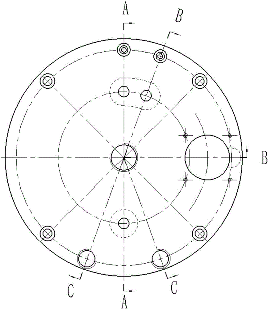
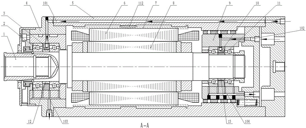
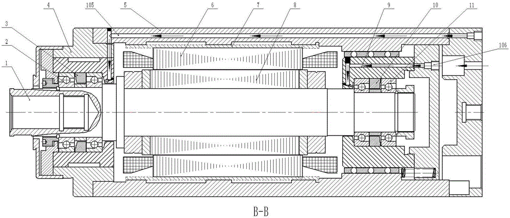
[0028] combine figure 1 , 2 , 3, 4 and specific implementation examples, the present invention is further described:

[0029] The electric spindle of the present invention includes a mandrel 1, a front bearing 2, a front bearing chamber 4, a casing 5, a stator 6, a water jacket 7, a rotor 8, a rear bearing chamber 9, a rear bearing 10 and the like. The front and rear bearing chambers are connected through a housing 5, a stator 6 is fixed inside the housing...


PUM


Abstract

The invention discloses a high-speed oil-gas lubrication electric spindle achieving precise oil supplying, and belongs to the technical field of electric spindles. The overall electric spindle comprises a shell, and a stator is fixed in the shell; a front bearing chamber and a back bearing chamber are connected to the two ends of the shell respectively, and two bearings are connected in series in each bearing chamber, wherein the two bearings are separated through an inner bearing isolation pad and an outer bearing isolation pad; a central spindle is supported by the front bearings and the back bearings and provided with a rotor matched with the stator; each bearing is provided with an oil-gas lubrication oil line; annular cooling grooves are formed in the front bearing chamber and the shell respectively; the bearing shell is provided with oil-gas inlets and an oil-gas outlet, an oil-gas pipeline penetrates through the shell, the bearing chambers and the outer bearing isolation pads, the tail end of the pipeline is provided with an oil-gas nozzle, and each bearing is provided with an independent oil delivery line, an independent nozzle and an independent oil return line. Accordingly, by designing the independent oil-gas lubrication oil lines, nozzles and oil return lines, precise control over oil-gas lubrication parameters of the bearings is achieved, the lubricating effect of the bearings is improved, and the performance of the electric spindle is enhanced.

Description

technical field [0001] The invention relates to an electric spindle, in particular to a high-speed electric spindle using oil-air lubrication for precise oil supply. Background technique [0002] With the development of high-speed machining technology, the manufacturing industry has higher and higher requirements on the speed of machine tools. As the core component of the machine tool, the electric spindle is also developing towards high speed. The rotary motion of the electric spindle mainly depends on the supporting bearings at both ends of the mandrel. The speed and bearing capacity of the bearings directly affect the performance of the electric spindle. [0003] Lubrication is a key factor affecting the performance of bearings. Traditional electric spindle bearing lubrication methods are mostly grease lubrication and oil lubrication. Most of these lubrication methods are excessive lubrication, which not only wastes resources, but also generates additional frictional to...

Claims


Application Information

Patent Timeline
Patent Type & Authority Applications(China)
IPC IPC(8): B23B19/02B23Q11/12
CPCB23Q1/70B23Q11/122B23Q11/123B23Q11/127
Inventor 刘牧原周广辉王建郭峰
Owner 泰安海纳轴研科技有限公司
Why Eureka
Try Eureka