

Efficient energy-saving generatrix groove
A busway and high-efficiency technology, applied in the field of busway, can solve the problems of easy infiltration of water in the connecting part, affecting the safe operation of equipment, increasing the installation workload, etc., to achieve the effect of convenient manufacturing and installation, simple structure and good heat dissipation effect.
Active Publication Date: 2017-06-13
鼎圣集团有限公司
View PDF5 Cites 4 Cited by
- Summary
- Abstract
- Description
- Claims
- Application Information
AI Technical Summary
Problems solved by technology
[0003] In the bus duct system, the plug-in device plays an important role as a device for distributing electric energy. With the development of bus duct technology, the traditional manufacturing method of the plug-in device is generally to perform special treatment on the internal conductor of the bus duct at the plug-in position. (such as intermediate expansion, welding or riveting inserts, etc.), the plug-in box is fixed on the busway body, but due to the complexity of the manufacturing process, low production efficiency, and high manufacturing costs, some engineers and technicians in the industry also Trying to find a more efficient manufacturing process, even though the concept of connector type has sprouted, the fixing of this type of plug-in box has become a big problem
[0004] Moreover, the shell structure of the existing busway is usually composed of upper and lower cover plates and a C-shaped side plate. Although the side plates are processed by aluminum plates, the heat dissipation area is limited.
This structure not only affects the appearance of the shell, but also has a large error during the processing of the shell, which causes water to easily seep into the connecting part during use and affects the safe operation of the equipment. Therefore, it is usually necessary to drill the joint between the side plate and the top plate Sealant, which further increases the installation workload, and during the operation of the equipment, the equipment will generate a lot of heat, and the heat dissipation effect is not ideal
Method used
View moreImage
Smart ImageViewing Examples

Examples
Embodiment Construction
[0061] In order to make the technical solution of the present invention clearer, the present invention will be further described below in conjunction with the accompanying drawings. Any solution obtained by equivalent replacement and conventional reasoning of the technical features of the technical solution of the present invention falls within the protection scope of the present invention.
Login to View More PUM
 Abstract
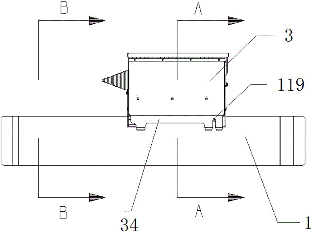
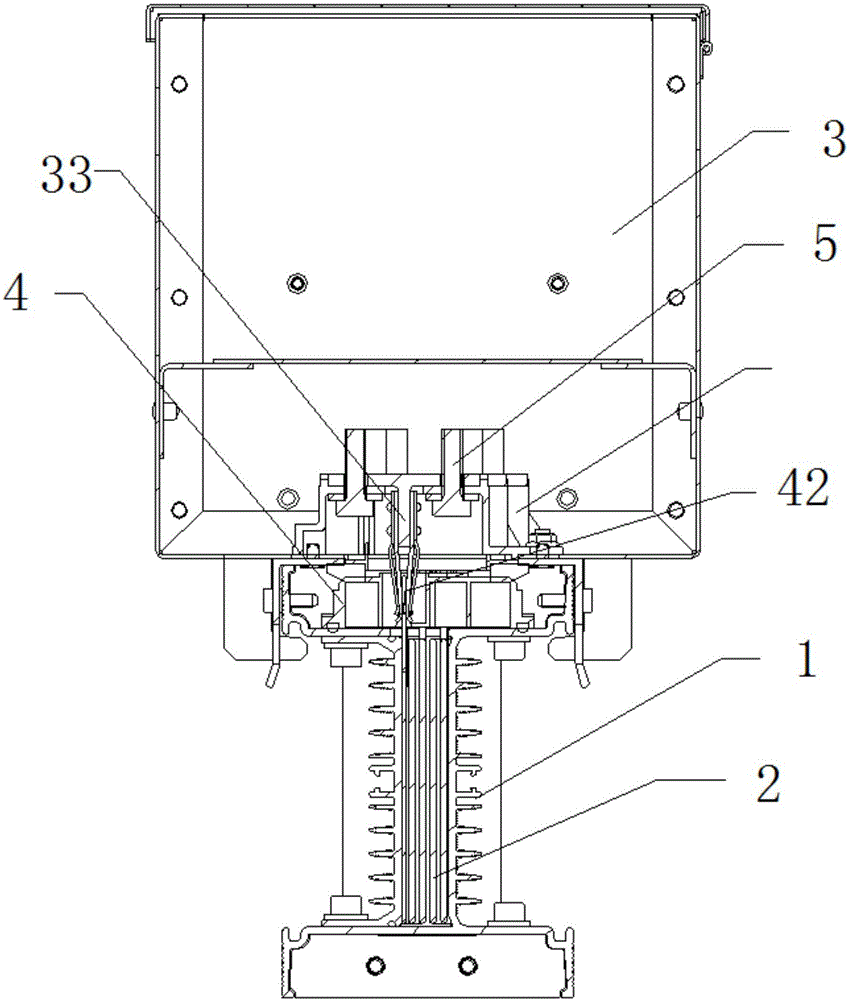
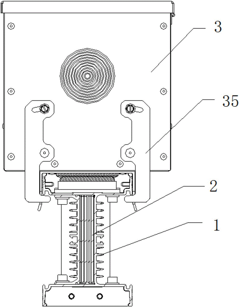
The invention relates to an efficient energy-saving generatrix groove. The efficient energy-saving generatrix groove comprises a generatrix groove shell body, a plurality of bus bars arranged in the generatrix groove shell body, a jack box, a socket device and a cable wiring column; the shell body has a simple structure, is convenient to mount and has a good heat dissipation effect; meanwhile, the jack box with a high safety performance is arranged so that accurate, convenient and rapid jacking of the jack box is ensured; and meanwhile, the safety and reliability of hot plugging are ensured.
Description
technical field [0001] The invention relates to a bus duct, in particular to an efficient energy-saving bus duct. Background technique [0002] With the advancement of the technology industry and the development of private industry and commerce, the requirements for the safety, stability, and indoor space allocation and utilization of high-power transmission are also increasing. Generally, most of them are installed in industrial buildings or buildings that use high-power. Cables are used to transmit high power, and under the emphasis on safety, the use of cables to transmit power has gradually failed to meet the considerations of safety and space allocation. Slowly replace the cables that were heavy and complicated to install in the past, and the electrical busway saves the configuration space compared with the cables. [0003] In the bus duct system, the plug-in device plays an important role as a device for distributing electric energy. With the development of bus duct t...
Claims
Login to View More Application Information
Patent Timeline
 Patent Type & AuthorityApplications(China)
IPC IPC(8): H02G5/08H02G5/10
CPCH02G5/08H02G5/10
Inventor李立军张开银
Owner鼎圣集团有限公司