Automatic cutting device for door-window manufacturing material

An automatic cutting device, a technology for doors and windows, applied in metal processing and other directions, can solve the problems of low work efficiency, uneven cutting surface, complex structure, etc., and achieve the effect of simple structure

Inactive Publication Date: 2017-06-20
响水县泽州开发有限公司
View PDF7 Cites 3 Cited by
  • Summary
  • Abstract
  • Description
  • Claims
  • Application Information

AI Technical Summary

Problems solved by technology

[0002] When making doors and windows, it is usually necessary to cut the whole long material into multiple and short materials, and most of the time, these materials are all equal in length. In the prior art, they are cut manually, which is characterized by low work efficiency and labor High strength, time-consuming and labor-intensive, and the existing cutting device has the characteristics of large volume and complex structure, so it is urgent to develop a material cutting device with high work efficiency, reduced labor intensity, and time-saving and labor-saving
[0003] The main working principle of the cutting device introduced in the invention "A Cutting Device for Making Materials of Plastic Steel Doors and Windows" (authorized announcement number: CN 205766367 U) is: after the material withstands the wedge block, the wedge block moves to the left, so that the lifting rod goes up Moving, under the action of the lever principle, the cutting machine rotates downward to cut, but its disadvantage is that when the cutting machine rotates downward, the cutting piece also rotates around the rotating shaft, so that the cutting surface is not smooth, and the material is continuous Moving to the left will exert a vertical force on the cutting piece, and the cutting piece is easy to wear

Method used


Image

  • Automatic cutting device for door-window manufacturing material
  • Automatic cutting device for door-window manufacturing material
  • Automatic cutting device for door-window manufacturing material

Examples


Embodiment Construction

[0016] The following will clearly and completely describe the technical solutions in the embodiments of the present invention with reference to the accompanying drawings in the embodiments of the present invention. Obviously, the described embodiments are only some, not all, embodiments of the present invention. Based on the embodiments of the present invention, all other embodiments obtained by persons of ordinary skill in the art without making creative efforts belong to the protection scope of the present invention.

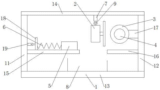
[0017] Such as Figure 1-Figure 3 As shown, an automatic cutting device for door and window making materials of the present invention has the following structure: the bracket 1 includes a left side plate 11, a right side plate 12, a bottom plate 13, and a top plate 14, and a limit slide plate is installed on the left side plate 11 15. The limit slider 5 is installed on the limit slider 15 and can move freely along the left and right directions. A compression s...


PUM


Abstract

The invention discloses an automatic cutting device for door and window materials. A limit slide is installed on the left side plate. The limit slide is installed on the limit slide and can move freely along the left and right directions. A compression spring is installed between the left side plates; a force sensor is installed at the end of the compression spring; a placement plate is installed on the right side plate, the height of the placement plate is the same as that of the limit slide plate; A motor bracket is arranged above the placing plate, the motor is fixedly installed on the motor bracket, and a pressure roller is fixedly installed on the output shaft of the motor; a hydraulic cylinder is installed on the top plate, and the tail of the hydraulic cylinder is fixedly installed on the top plate. The push rod portion of the hydraulic cylinder is fixedly connected with a cutting machine, and the cutting piece on the cutting machine is parallel to the right side plate. The invention has the advantages of simple structure, can adjust multiple different cutting lengths and cutting certificates, and can also cut oblique angles.

Description

technical field [0001] The invention belongs to the technical field of door and window manufacturing equipment, and in particular relates to an automatic cutting device for door and window manufacturing materials. Background technique [0002] When making doors and windows, it is usually necessary to cut the whole long material into multiple and short materials, and most of the time, these materials are all equal in length. In the prior art, they are cut manually, which is characterized by low work efficiency and labor High strength, time-consuming and labor-intensive, and the existing cutting device has the characteristics of large volume and complex structure. Therefore, it is urgent to develop a material cutting device with high work efficiency, which can reduce labor intensity and save time and labor. [0003] The main working principle of the cutting device introduced in the invention "A Cutting Device for Making Materials of Plastic Steel Doors and Windows" (authorized...

Claims


Application Information

Patent Timeline
Patent Type & Authority Applications(China)
IPC IPC(8): B26D1/157B26D7/06B26D5/04B26D7/32B26D5/20
CPCB26D1/157B26D5/04B26D5/20B26D7/06B26D7/32
Inventor 吉华
Owner 响水县泽州开发有限公司
Why Eureka
Try Eureka