Ceramic tile turnover and automatic waxing equipment

A ceramic tile and automatic technology, applied in the direction of spraying device, etc., can solve the problems of easy reduction of manpower waxing, low waxing efficiency, low cost of waxing, automatic continuity of tile waxing, etc., and achieve the effect of ensuring turnover and high waxing efficiency.

Inactive Publication Date: 2017-07-04
湖州裕尚卫浴有限公司
View PDF1 Cites 10 Cited by
  • Summary
  • Abstract
  • Description
  • Claims
  • Application Information

AI Technical Summary

Problems solved by technology

[0006] The purpose of the present invention is to overcome the shortcomings of the prior art and overcome the problems that tile waxing cannot achieve automatic continuity, low waxing efficiency and manpower consumption, and wax is easy to fall on the tiles, and waxing is uneven.

Method used


Image

  • Ceramic tile turnover and automatic waxing equipment
  • Ceramic tile turnover and automatic waxing equipment
  • Ceramic tile turnover and automatic waxing equipment

Examples


Embodiment 1

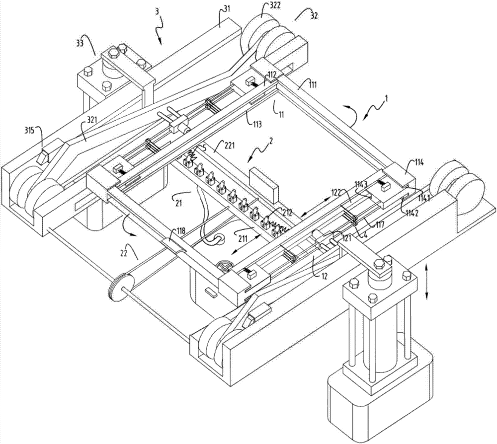
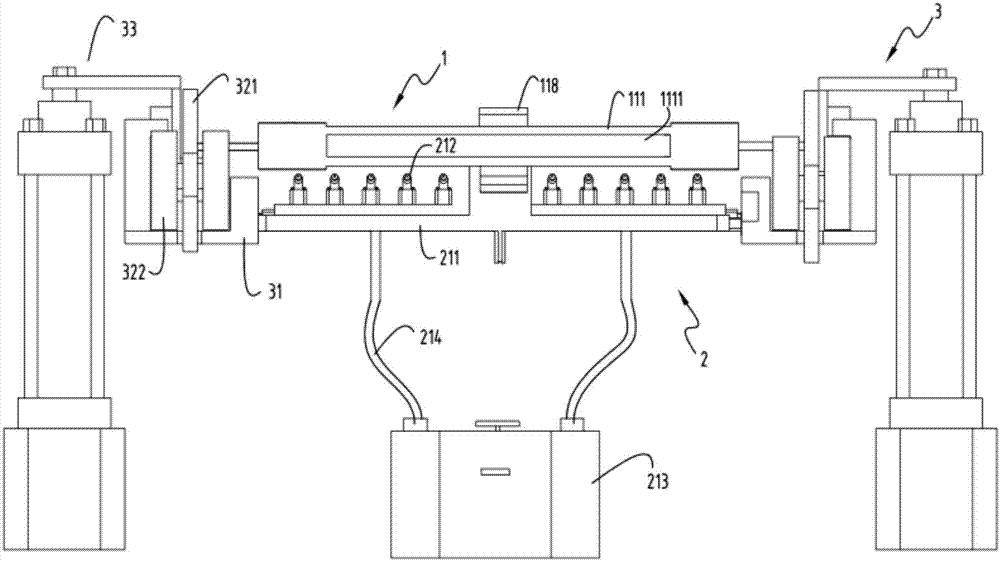
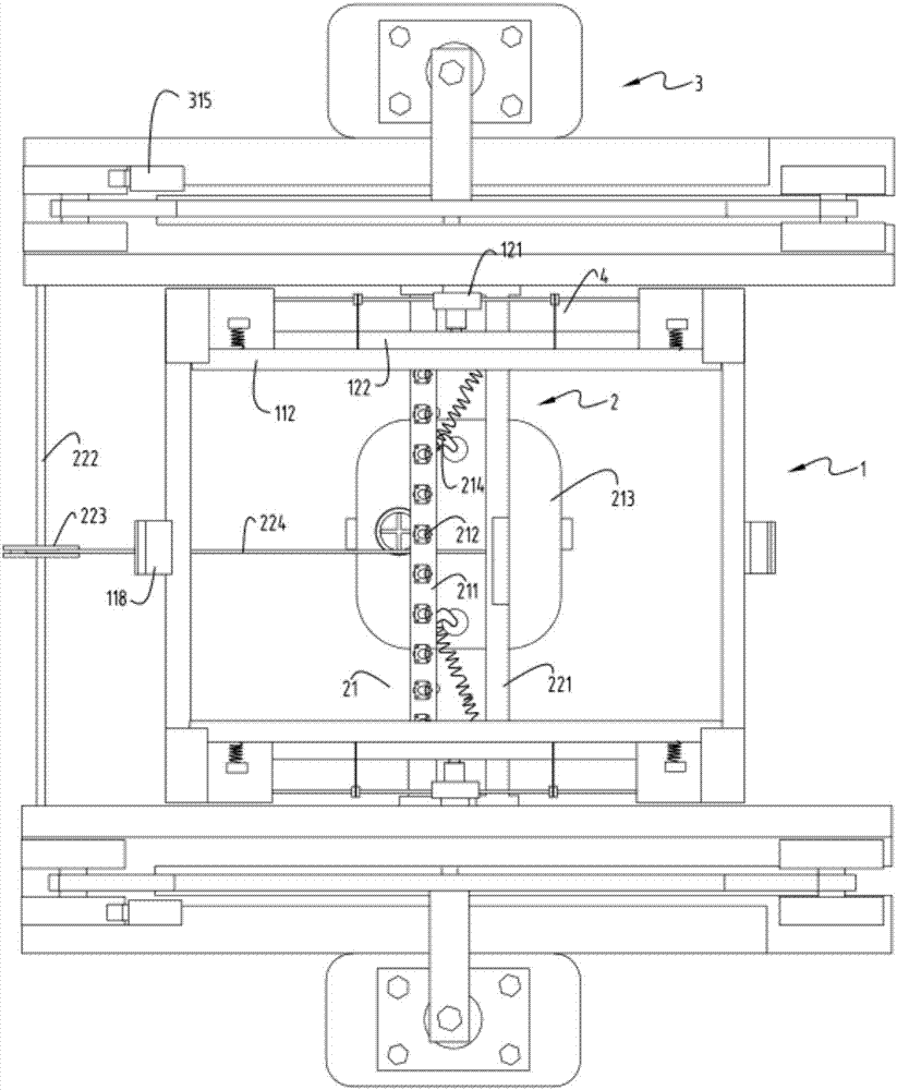
[0051] figure 1 Schematic diagram of the automatic waxing equipment for tile flipping, figure 2 Schematic diagram of the front view of the automatic waxing equipment for tile flipping, image 3 A top view schematic diagram of automatic waxing equipment for tile flipping, Figure 4 It is a schematic diagram of the structure of the sliding wax spraying part and the support seat, Figure 5 Schematic diagram of the enlarged structure of the sliding restraint device, Figure 6 Schematic diagram of the structure during the flipping process of the automatic waxing equipment for tile flipping, Figure 7 is a structural schematic diagram of reset device a or reset device b, Figure 8 Schematic diagram of the structure of the automatic waxing equipment for tile turning when the roller is about to contact the sliding limit device during the turning process, Figure 9 It is a schematic diagram of the structure when holding the positioning part to clamp the tiles, Figure 10 Enlargi...

Embodiment 2

[0068] Such as figure 1 , figure 2 , image 3 , Figure 4 , Figure 5 , Figure 6 , Figure 7 , Figure 8 , Figure 9 , Figure 10 , Figure 11 , Figure 12 , Figure 13 , Figure 14 as well as Figure 15 As shown, the components that are the same as or corresponding to those in the first embodiment are marked with the corresponding reference numerals in the first embodiment. For the sake of simplicity, only the differences from the first embodiment will be described below. The difference between the second embodiment and the first embodiment is that the clamping block 122 is linked with the support block a112 and the support block b113 through the pulley mechanism 4, and the pulley mechanism 4 includes a The pulley b41, the pulling rope a42 that goes around the pulley b41 and is fixedly connected to the clamping block 122 and the support block a112 at both ends, the pulley c43, and the pulley c43 that goes around the pulley c43 and connects the two ends to the c...


PUM


Abstract

The invention relates to ceramic tile turnover and automatic waxing equipment which comprises a clamping and locating part, a sliding wax spray part and a rotating part. The clamping and locating part comprises a supporting mechanism used for locating and supporting ceramic tiles to be turned over and waxed, and a clamping mechanism used for clamping the ceramic tiles. The sliding wax spray part is used for waxing the surfaces of the ceramic tiles and comprises a wax spray mechanism and a transmission mechanism. The rotating part is used for driving the clamping and locating part and the ceramic tiles to be turned over together and meanwhile driving the wax spray mechanism through the transmission mechanism to move in the front-and-back direction to wax the ceramic tiles. The rotating part comprises a supporting seat, a turnover device fixedly connected with the supporting mechanism and a lifting device used for driving the turnover device to slide and be turned over along the supporting seat. The wax spray mechanism comprises a wax spray seat and multiple wax spray heads. The problems that ceramic tile waxing cannot be automatic and continuous, waxing efficiency is low, manpower is consumed, wax is prone to dripping onto the ceramic tiles, and waxing is not uniform are solved.

Description

technical field [0001] The invention relates to the technical field of waxing equipment, in particular to an automatic waxing equipment for tile flipping. Background technique [0002] Ceramic tiles are commonly used materials in the daily decoration process. Ceramic tiles can make the whole decoration brighter, tidy and easy to clean. During the use of ceramic tiles, people often wax the surface of ceramic tiles. The film formed after waxing tiles can prevent moisture and The role of dust, while enhancing the aesthetics of tiles. In addition, there is a protective wax, which can effectively prevent the surface of the tiles from being damaged during use or transportation, and affect the appearance of the tiles. The existing waxing on the tiles is mainly done manually, and there is a disadvantage of uneven waxing. , and the waxing efficiency is low, especially when dealing with a large number of tiles to be waxed and protected before leaving the factory to prevent damage to ...

Claims


Application Information

Patent Timeline
Patent Type & Authority Applications(China)
IPC IPC(8): B05B13/02B05B13/04
CPCB05B13/0228B05B13/041B05B13/0442
Inventor 陆惠明
Owner 湖州裕尚卫浴有限公司
Why Eureka
Try Eureka