Ceramic tile surface waxing treatment production line

A production line and wax treatment technology, which is applied to the surface pretreatment, the device for coating liquid on the surface, the spray device, etc., can solve the problems of lack of integrated continuous processing, uneven manpower waxing, low efficiency and low consumption, etc. Achieve the effect of high waxing efficiency, low production cost and improved efficiency

Inactive Publication Date: 2017-07-11
湖州裕尚卫浴有限公司
View PDF1 Cites 11 Cited by
  • Summary
  • Abstract
  • Description
  • Claims
  • Application Information

AI Technical Summary

Problems solved by technology

[0006] The purpose of the present invention is to address the deficiencies of the prior art, and overcome the problems of tile waxing and wax surface polishing that do not have the function of integrated continuous processing, low efficiency, labor-intensive waxing, and uneven waxing.

Method used


Image

  • Ceramic tile surface waxing treatment production line
  • Ceramic tile surface waxing treatment production line
  • Ceramic tile surface waxing treatment production line

Examples


Embodiment 1

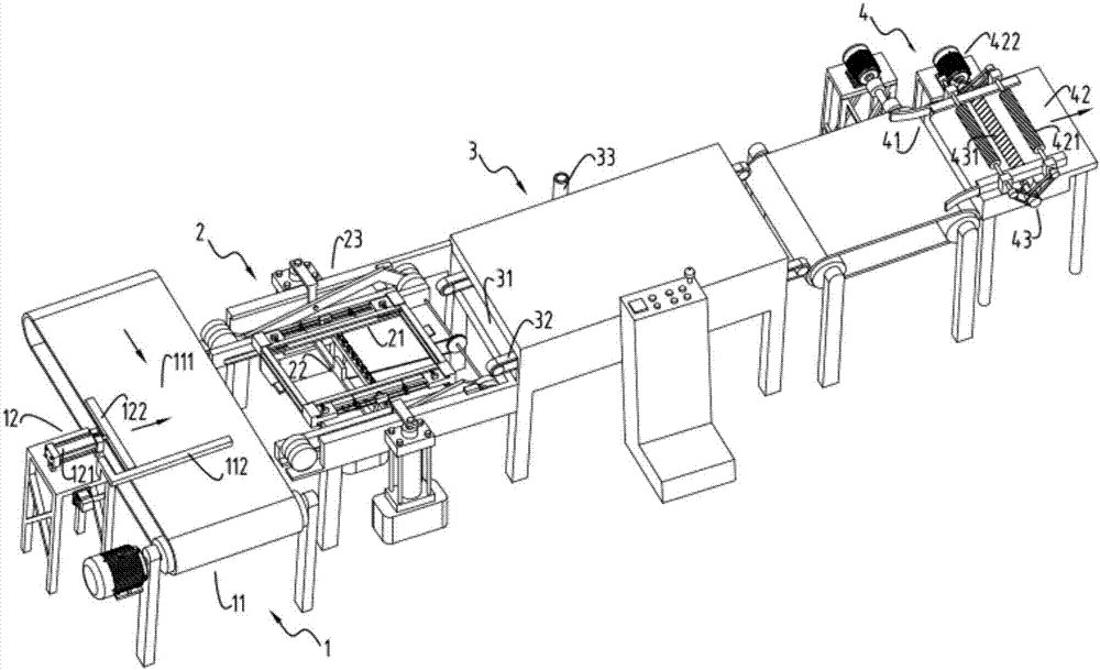
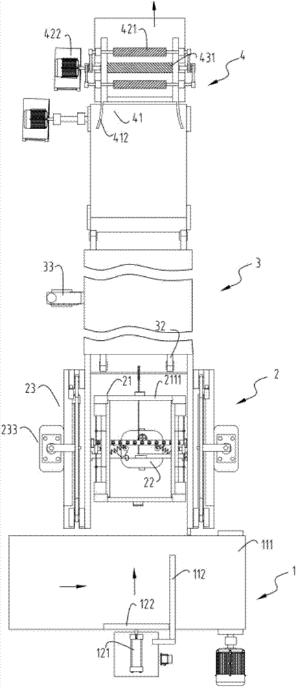
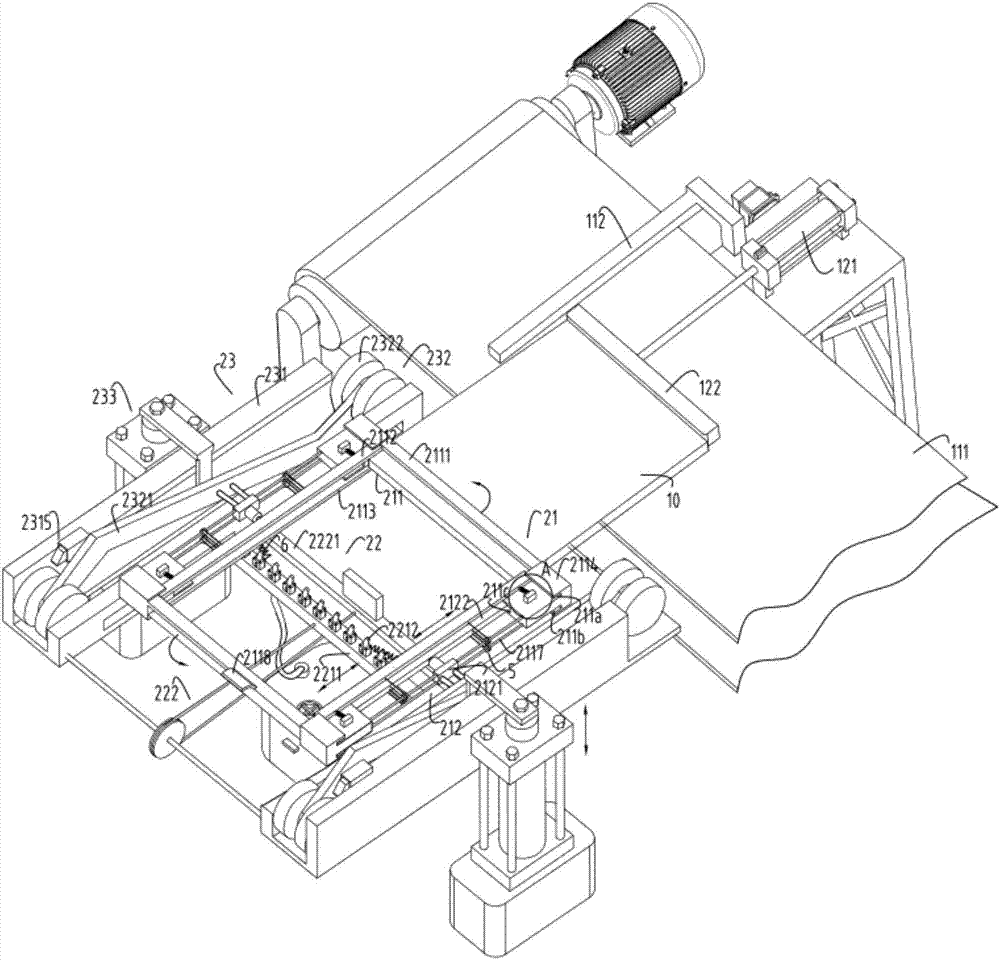
[0062] figure 1 Schematic diagram of the production line for waxing the surface of ceramic tiles, figure 2 The schematic diagram of the top view of the waxing treatment production line for the surface of ceramic tiles, image 3 Schematic diagram of the structure for positioning the feeding part and turning the waxing part, Figure 4 is an enlarged schematic diagram of reset device a or reset device b, Figure 5 Schematic diagram of the structure during the inversion process of the waxing part of the inversion, Figure 6 Schematic diagram of dismantling part of the mechanism for flipping the waxing part, Figure 7 Schematic diagram of the enlarged structure of the sliding restraint device, Figure 8 It is a schematic diagram of the structure when the clamping positioning mechanism clamps the tiles, Figure 9 The schematic diagram of the enlarged structure of the pulley mechanism, Figure 10 It is a schematic diagram of the structure when the clamping block clamps the til...

Embodiment 2

[0093] Such as figure 1 , figure 2 , image 3 , Figure 4 , Figure 5 , Figure 6 , Figure 7 , Figure 8 , Figure 9 , Figure 10 , Figure 11 , Figure 12 , Figure 13 , Figure 14 as well as Figure 15 As shown, the components that are the same as or corresponding to those in the first embodiment are marked with the corresponding reference numerals in the first embodiment. For the sake of simplicity, only the differences from the first embodiment will be described below. The difference between the second embodiment and the first embodiment is that the clamping block 2122 is linked with the support block a2112 and the support block b2113 through the pulley mechanism 5, and the pulley mechanism 5 includes a The pulley b51, the pulling rope a52 that goes around the pulley b51 and is fixedly connected to the clamping block 2122 and the support block a2112 at both ends, the pulley c53, and the pulley c53 that goes around the pulley c53 and connects the two ends to ...

Embodiment 3

[0095] Such as figure 1 , figure 2 , image 3 , Figure 4 , Figure 5 , Figure 6 , Figure 7 , Figure 8 , Figure 9 , Figure 10 , Figure 11 , Figure 12 , Figure 13 , Figure 14 as well as Figure 15 As shown, the parts that are the same as or corresponding to those in the second embodiment are marked with the corresponding reference numerals in the second embodiment. For the sake of simplicity, only the differences from the second embodiment will be described below. The difference between the third embodiment and the second embodiment is: the positioning device 41 includes a limit chute 411 and a guide block 412 arranged at the entrance of the limit chute 411; the power device 42 includes a driving wheel 421 and Motor 422 ; the grinding device 43 includes a grinding roller 431 , and both the grinding roller 431 and the driving wheel 421 work under the drive of the motor 422 .

[0096] The moving power of the ceramic tile 10 in the grinding process is provi...


PUM


Abstract

The invention relates to a tile surface waxing treatment production line, which includes a positioning feeding part, the positioning feeding part is used to position and push the delivered tiles backward; a turning waxing part is arranged on the Positioning the rear end of the feeding part, the turning waxing part is used to wax the tiles pushed by the positioning feeding part; the drying part, the drying part is arranged at the rear end of the turning waxing part, and the drying part is used for It is used to dry the ceramic tiles output after being waxed by the turned waxing part; the polishing part is arranged at the rear end of the drying part, and the polishing part is used to perform surface waxing on the ceramic tiles output after the drying process of the drying part Polishing of the first layer; it overcomes the problems of tile waxing and wax surface polishing that do not have the function of integrated continuous processing, low efficiency and labor-intensive waxing process and uneven waxing.

Description

technical field [0001] The invention relates to the technical field of waxing equipment, in particular to a tile surface waxing treatment production line. Background technique [0002] Ceramic tiles are commonly used materials in the daily decoration process. Ceramic tiles can make the whole decoration brighter, tidy and easy to clean. During the use of ceramic tiles, people often wax the surface of ceramic tiles. The film formed after waxing tiles can prevent moisture and The role of dust, while enhancing the aesthetics of tiles. In addition, there is a protective wax, which can effectively prevent the surface of the tiles from being damaged during use or transportation, and affect the appearance of the tiles. The existing waxing on the tiles is mainly done manually, and there is a disadvantage of uneven waxing. , and the low efficiency of waxing, especially when dealing with large quantities of tiles to be waxed before leaving the factory to prevent damage to the surface ...

Claims


Application Information

Patent Timeline
Patent Type & Authority Applications(China)
IPC IPC(8): B05B13/02B05B13/04B05D3/04B05D3/00
CPCB05B13/0228B05B13/041B05B13/0442B05D3/007B05D3/0406
Inventor 陆惠明
Owner 湖州裕尚卫浴有限公司
Why Eureka
Try Eureka