Handle-driven lock body

A handle and lock body technology, which is applied in handle connection, building locks, door/window accessories, etc., can solve the problems of destroying the lock body and the key broken in the lock cylinder, etc., and achieve the goal of ensuring safety, exquisite design and guaranteed life Effect

Active Publication Date: 2017-08-22
薛建能
View PDF6 Cites 3 Cited by
  • Summary
  • Abstract
  • Description
  • Claims
  • Application Information

AI Technical Summary

Problems solved by technology

[0003] The technical problem to be solved by the present invention is to provide a handle-driven lock body, so as to solve the problem that in the prior art, the door can only be opened with a key and sometimes the key is broken in the lock cylinder, and the inside of the lock body will be damaged when the handle is forcibly turned. parts problem

Method used


Image

  • Handle-driven lock body
  • Handle-driven lock body
  • Handle-driven lock body

Examples


Embodiment Construction

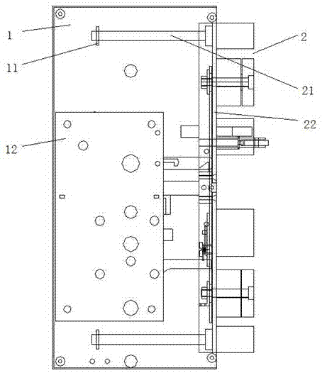
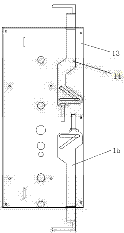
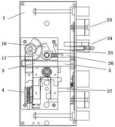
[0053] Such as figure 1 , figure 2 , image 3 , Figure 4 , Figure 5 , Figure 6 , Figure 7 , Figure 8 , Figure 9 , Figure 10 , Figure 11 , Figure 12 , Figure 13 , Figure 14 , Figure 15 , Figure 16 , Figure 17 , Figure 18 , Figure 19 , Figure 20 , Figure 21 , Figure 22 , Figure 23 and Figure 24As shown, a handle-driven lock body includes a bottom plate 1, a dead bolt 2, a pulling device, a lock cylinder device and a handle; The left and right sides of the pulling device are respectively fixedly connected with the pull rod 5 and the dead bolt 2, the dead bolt bottom plate 22 is located on the same side of the pull rod 5 and is fixedly connected with the guide rod 21, the bottom plate 1 is provided with a support block 11, and the guide rod 21 is slidably connected to the support On the block 11, the guide rod 21 is covered with a return spring, which is located between the deadbolt bottom plate 22 and the support block 11, the sky lock ...


PUM


Abstract

The invention discloses a handle-driven lock body comprising a bottom plate, a plurality of lock tongues, a pulling device, a lock cylinder device and a handle. A lock tongue bottom plate is movably connected to the edge of the right side of the bottom plate. A pulling rod in the pulling device and the lock tongues are fixedly connected on the left and right sides of the lock tongue bottom plate correspondingly. The handle and the lock cylinder device are arranged in the positions, above and below the pulling rod, of the bottom plate correspondingly. A rack dragging block in the pulling device is movably connected on the pulling rod and connected with the handle in a transmission mode. When the handle is rotated clockwise, the rack dragging block drives an unlocking sliding piece in the lock cylinder device to move toward the pulling rod through a transmission device; a dragging rod is movably connected on the pulling rod, and one end of the dragging rod extends into a dragging hole formed in the rack dragging block under pushing of the end of the unlocking sliding piece; and the rack dragging block drives the pulling rod to move to pull the lock tongues back to the lock body. The lock tongues comprise the two pick-proof lock tongues and the tough lock tongue. The conception is ingenious, and the handle is rotated to drive a gear to complete all actions.

Description

technical field [0001] The invention relates to a lock body, in particular to a handle-driven lock body. Background technique [0002] The lock body is one of the components of the lock. There are many kinds of lock bodies, such as one-way lock body, three-way lock body, and four-way lock body. Generally used on anti-theft doors, it is responsible for the basic anti-theft work of anti-theft doors. The lock cylinder controls the operation of the lock body, and the lock body is responsible for opening and locking the doors and windows, and plays an important role in anti-theft. The current lock body can only be opened with a key outside the door, and after the door is used for a long time, there will be greater friction between the bolt and the door frame, as well as friction between the parts inside the lock body, and the size of the key is too small to withstand Large torsional force sometimes causes the key to break in the lock cylinder; and the transmission between the ha...

Claims


Application Information

Patent Timeline
Patent Type & Authority Applications(China)
IPC IPC(8): E05B17/20E05B15/10E05B15/00E05B3/00E05B63/14
CPCE05B3/00E05B15/00E05B15/10E05B17/2069E05B63/146
Inventor 薛建能
Owner 薛建能
Why Eureka
Try Eureka