A handle-driven lock body

A handle and lock body technology, which is applied in handle connection, building locks, construction, etc., can solve the problems of destroying the lock body and the key broken in the lock cylinder, etc., and achieves the effect of exquisite design

Active Publication Date: 2022-03-18
薛建能
View PDF0 Cites 0 Cited by
  • Summary
  • Abstract
  • Description
  • Claims
  • Application Information

AI Technical Summary

Problems solved by technology

[0003] The technical problem to be solved by the present invention is to provide a handle-driven lock body, so as to solve the problem that in the prior art, the door can only be opened with a key and sometimes the key is broken in the lock cylinder, and the inside of the lock body will be damaged when the handle is forcibly turned. parts problem

Method used


Image

  • A handle-driven lock body
  • A handle-driven lock body
  • A handle-driven lock body

Examples


Embodiment Construction

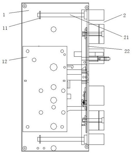
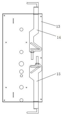
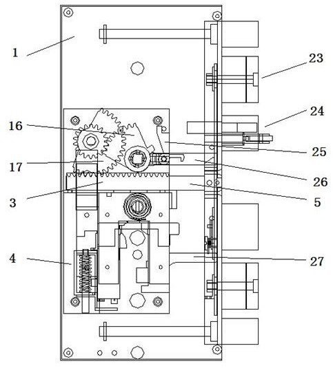
[0052] Such as figure 1 , figure 2 , image 3 , Figure 4 , Figure 5 , Image 6 , Figure 7 , Figure 8 , Figure 9 , Figure 10 , Figure 11 , Figure 12 , Figure 13 , Figure 14 , Figure 15 , Figure 16 , Figure 17 , Figure 18 , Figure 19 , Figure 20 , Figure 21 , Figure 22 , Figure 23 and Figure 24As shown, a handle drive lock body, including a bottom plate 1, a locking tongue 2, a pulling device, a locking core device, and a handle; the right side portion of the bottom plate 1 is attached to the lock panel 22, the locking plate 22 The left and right sides respectively fixed the tie rod 5 and the locking tongue 2, and the lock tongue bottom plate 22 is fixed to the same side of the tie rod 5, and the bottom plate 1 is provided with a support block 11, and the guide bar 21 is slidably connected to the support. On the block 11, the guide bar 21 is sleeve, and the reset spring is located between the lock tongue bottom plate 22 and the support block 11, and the space lock rod 14 is slid on th...


PUM


Abstract

The invention discloses a handle-driven lock body, which comprises a bottom plate, a deadbolt, a pulling device, a lock cylinder device and a handle; The pull rod and the dead bolt in the pulling device are fixedly connected, and the handle and the lock cylinder device are respectively arranged on the bottom plate above and below the pull rod; Transmission connection; when the handle is turned clockwise, the rack drag block drives the unlocking slide in the lock cylinder device to move to the pull rod through the transmission device. The pull rod is movably connected with a drag rod, which is pushed by the end of the unlock slide 1. One end extends into the dragging hole set by the rack dragging block, and the rack dragging block drives the pull bar to move to pull the dead bolt back into the lock body; there are multiple dead bolts, including two tamper-proof bolts and One touches the dead bolt, and the present invention is conceived delicately, and all actions are driven by the handle turning the handle to drive the gear.

Description

Technical field [0001] The present invention relates to a lock body, and is specifically involved in a handler locking body. Background technique [0002] The lock body is one of the components of the lock, and there are many kinds of locks, commonly with one-way lock bodies, three-way lock bodies, four-way lock bodies, and the like. Generally used on the security door, responsible for the basic anti-theft work of security doors, the lock core is to control the lock body, the lock body is responsible for opening and locking the doors and windows and locking the role in theft. The current lock body can only be opened with a key outside the door, while the door is used in long-term use, the lock tongue and the door frame produces a large friction, and the friction between the parts inside the lock body, and the key size is small, and cannot withstand The larger torsion force sometimes generates the failure of the key to the lock core; and the transmission between the lock body and ...

Claims


Application Information

Patent Timeline
Patent Type & Authority Patents(China)
IPC IPC(8): E05B17/20E05B15/10E05B15/00E05B3/00E05B63/14
CPCE05B3/00E05B15/00E05B15/10E05B17/2069E05B63/146
Inventor 薛建能
Owner 薛建能
Why Eureka
Try Eureka