Drawer type paper roll box

A paper roll box and drawer-type technology, which is applied in the field of paper roll boxes, can solve the problems of poor safety of the cutter, inconvenient operation, pollution, etc., and achieve the effect of limiting waste, improving safety, and ensuring smooth cutting

Active Publication Date: 2017-10-10
嘉兴金旅燕科技有限公司
View PDF7 Cites 4 Cited by
  • Summary
  • Abstract
  • Description
  • Claims
  • Application Information

AI Technical Summary

Problems solved by technology

[0003] Existing paper roll boxes generally only include a box with an opening and a rotating shaft for installing paper rolls in the box. People make the paper roll rotate by pulling the toilet paper at the opening to wind the toilet paper out. During the process of pulling out the toilet paper People intentionally or unintentionally pulling the paper roll hard will cause a long part of the toilet paper to be outside the opening and be polluted or damp, resulting in waste of toilet paper, and those who are interested can pull the toilet paper all at once
When pulling out the paper towels from the paper roll box, both hands are required to tear the toilet paper, which is inconvenient to operate
[0004] At the same time, the existing paper rolls generally need to be provided with scoring lines on the paper to facilitate tearing and keep the tearing line flat. The existing paper roll boxes also have a method of cutting the paper by a cutter, but the existing paper roll boxes have a The cutter needs to be set on the outside of the paper roll box, so that the end of the paper roll is outside the paper roll box when it is used next time, but the cutter is located on the outside of the paper roll box and the safety is very poor

Method used


Image

  • Drawer type paper roll box
  • Drawer type paper roll box
  • Drawer type paper roll box

Examples


Embodiment Construction

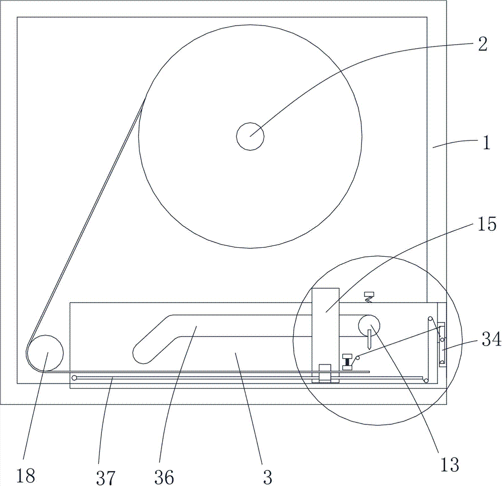
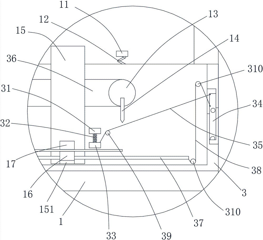
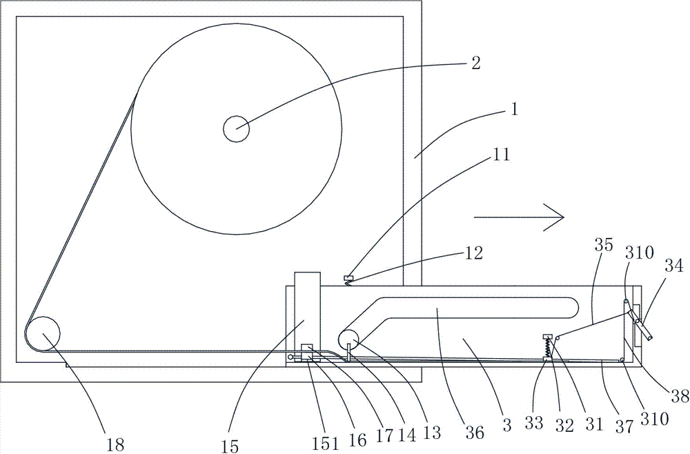
[0019] The present invention will be described in further detail below in conjunction with accompanying drawing and specific embodiment: see Figure 1 to Figure 6 , a drawer-type paper roll box, including a box body 1, a rotating shaft 2 for installing paper rolls is arranged in the box body 1, a drawer 3 is arranged at the bottom of the box body 1, and a second A fixed block 31, the clamping block 33 is connected to the bottom of the first fixed block 31 through the first spring 32, and the drawer 3 is provided with a drawer 34 whose middle part is rotatably connected with the drawer 3, and the drawer 34 A torsion spring (not shown in the figure) is arranged on the rotating shaft of the shaft, a first pull rope 35 is connected between the clamping block 33 and the pull plate 34, and guide holes 36 are arranged on both sides of the drawer 3, so that The box body 1 is provided with a second fixed block 11, the second fixed block 11 is connected with a sliding rod 13 pierced in ...


PUM


Abstract

The invention discloses a drawer type paper roll box which comprises a box body. A rotary shaft is arranged in the box body, a drawer is arranged at the bottom of the box body, first fixing blocks are arranged on two sides of the drawer, the lower portions of the first fixing blocks are connected with clamping blocks through first springs, a pull plate with the middle in rotary connection with the drawer is arranged on the drawer, a torsional spring is arranged on a rotary shaft of the pull plate, a first pull rope is connected between the clamping blocks and the pull plate, guiding holes are formed in two sides of the drawer, second fixing blocks are arranged in the box body, the lower portions of the second fixing blocks are connected with sliding rods penetrating into the guiding holes through second springs, and cutters are arranged at the bottoms of the sliding rods. The paper roll box capable of outputting paper in a fixed length mode can output paper according to the same length and perform automatic cutting, the paper roll box is more convenient and can be operated with one hand when being normally used by a user, toilet paper waste caused by non-normal usage is effectively limited, smooth cutting of paper rolls can be ensured without arranging cutting lines on the paper rolls, and the cutting safety of the paper roll box is improved.

Description

technical field [0001] The invention belongs to the technical field of paper roll boxes, in particular to a drawer type paper roll box. Background technique [0002] At present, toilet paper has been widely used in family toilets and public toilets. In public toilets, roll-packed toilet paper is commonly used. The paper roll box can effectively prevent the paper roll from being polluted or damp. [0003] Existing paper roll boxes generally only include a box with an opening and a rotating shaft for installing paper rolls in the box. People make the paper roll rotate by pulling the toilet paper at the opening to wind the toilet paper out. During the process of pulling out the toilet paper People intentionally or unintentionally pulling the paper roll hard will make a long part of the toilet paper outside the opening and be polluted or damp, resulting in waste of toilet paper, and those who are interested can finish the toilet paper at one time. When pulling out the paper tow...

Claims


Application Information

Patent Timeline
Patent Type & Authority Applications(China)
IPC IPC(8): A47K10/22
CPCA47K10/22
Inventor 王雅莲
Owner 嘉兴金旅燕科技有限公司
Why Eureka
Try Eureka