Drawer-type paper roll box

A paper roll box and drawer-type technology, which is applied in the field of paper roll boxes, can solve the problems of poor safety, pollution, and inconvenient operation of the cutter, and achieve the effects of limiting toilet paper waste, ensuring smooth cutting, and improving safety

Active Publication Date: 2017-10-13
XINCHANG YUANZHOU IND DESIGN CO LTD
View PDF6 Cites 2 Cited by
  • Summary
  • Abstract
  • Description
  • Claims
  • Application Information

AI Technical Summary

Problems solved by technology

[0003] Existing paper roll boxes generally only include a box with an opening and a rotating shaft for installing paper rolls in the box. People make the paper roll rotate by pulling the toilet paper at the opening to wind the toilet paper out. During the process of pulling out the toilet paper People intentionally or unintentionally pulling the paper roll hard will cause a long part of the toilet paper to be outside the opening and be polluted or damp, resulting in waste of toilet paper, and those who are interested can pull the toilet paper all at once
When pulling out the paper towels from the paper roll box, both hands are required to tear the toilet paper, which is inconvenient to operate
[0004] At the same time, the existing paper rolls generally need to be provided with scoring lines on the paper to facilitate tearing and keep the tearing line flat. The existing paper roll boxes also have a method of cutting the paper by a cutter, but the existing paper roll boxes have a The cutter needs to be set on the outside of the paper roll box, so that the end of the paper roll is outside the paper roll box when it is used next time, but the cutter is located on the outside of the paper roll box and the safety is very poor

Method used


Image

  • Drawer-type paper roll box
  • Drawer-type paper roll box
  • Drawer-type paper roll box

Examples


Embodiment Construction

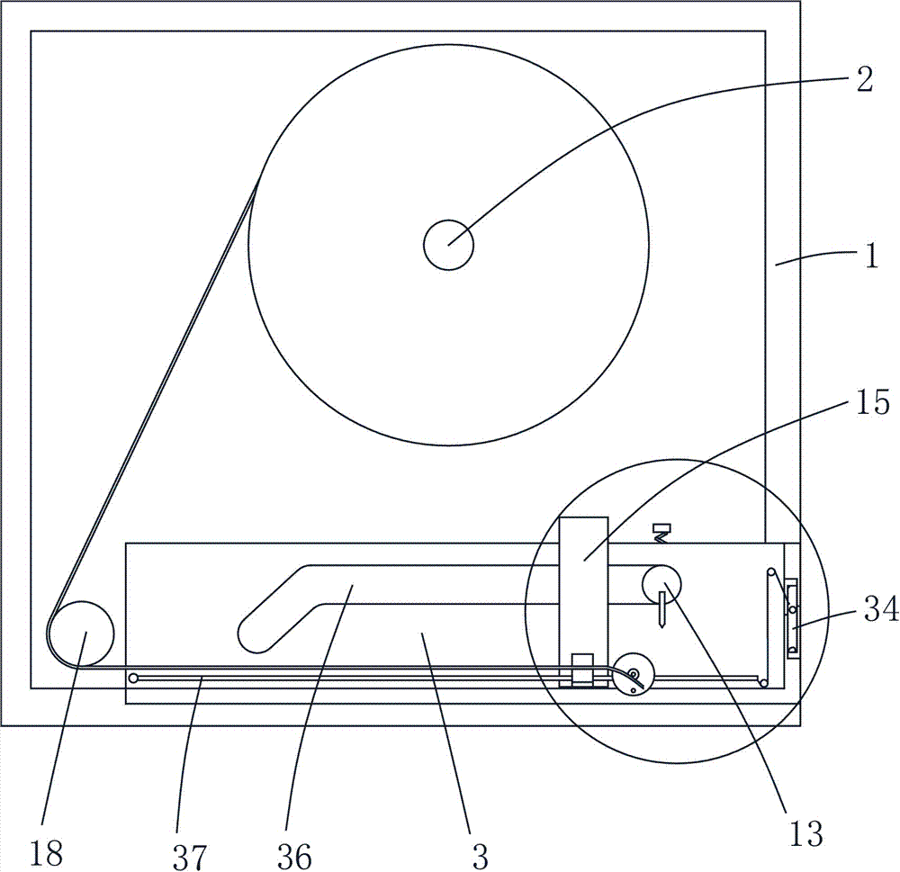
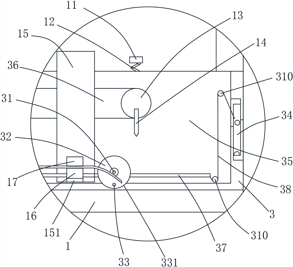
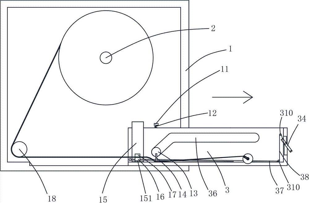
[0019] The present invention will be described in further detail below in conjunction with accompanying drawing and specific embodiment: see Figure 1 to Figure 6 , a drawer type paper roll box, including a box body 1, a rotating shaft 2 for installing paper rolls is arranged in the box body 1, a drawer 3 is arranged at the bottom of the box body 1, and rolls are installed on both sides of the drawer 3. Around the shaft 31, the winding shaft 31 is connected with a rotating disk 32 through a one-way bearing, the rotating disk 32 is provided with a winding rod 33, and the winding shaft 31 located outside the drawer 3 is fixed with a second A pulley 311, the outside of the drawer 3 is also rotatably provided with a second pulley 39, the first pulley 311 and the second pulley 39 are driven by the belt 4, and the second pulley 39 is coaxially fixed with a gear 391, so The box body 1 is provided with a rack 110 matching the gear 391, guide holes 36 are provided on both sides of the ...


PUM


Abstract

The invention discloses a drawer-type paper roll box, comprising a box body; a spindle for mounting a paper roll is disposed in the box body, a drawer is arranged at the bottom of the box body, a winding shaft is rotationally arranged on each side of the drawer, the winding shafts are connected with a rotary disc through unidirectional bearings, a winding rod is arranged on the rotary disc, a first pulley is fixed to the winding shaft at the outer side of the drawer, a second pulley is also rotationally arranged at the outer side of the drawer, the first pulley and the second pulley are driven through a belt, a gear is coaxially fixed to the second pulley, the box body is provided with a rack matching with the gear, two sides of the drawer are provided with guide holes, a first fixing block is arranged in the box body, a sliding rod penetrating the guide holes is connected to the bottom of the first fixing block through a first spring, and a cutter is arranged at the bottom of the sliding rod. The drawer-type paper roll box is more convenient for a user to use normally and is operable by one hand, and waste of tissues in non-normal use is effectively limited.

Description

technical field [0001] The invention belongs to the technical field of paper roll boxes, in particular to a drawer type paper roll box. Background technique [0002] At present, toilet paper has been widely used in family toilets and public toilets. In public toilets, roll-packed toilet paper is commonly used. The paper roll box can effectively prevent the paper roll from being polluted or damp. [0003] Existing paper roll boxes generally only include a box with an opening and a rotating shaft for installing paper rolls in the box. People make the paper roll rotate by pulling the toilet paper at the opening to wind the toilet paper out. During the process of pulling out the toilet paper People intentionally or unintentionally pulling the paper roll hard will make a long part of the toilet paper outside the opening and be polluted or damp, resulting in waste of toilet paper, and those who are interested can finish the toilet paper at one time. When pulling out the paper tow...

Claims


Application Information

Patent Timeline
Patent Type & Authority Applications(China)
IPC IPC(8): A47K10/36A47K10/22
CPCA47K10/22A47K10/36
Inventor 王雅莲
Owner XINCHANG YUANZHOU IND DESIGN CO LTD
Why Eureka
Try Eureka