
Separable connector used for intelligent power grid monitoring system
A technology for separating connectors and monitoring systems, which is applied in the direction of connecting and connecting device components, instruments, etc., and can solve problems such as difficult sound monitoring and light monitoring
- Summary
- Abstract
- Description
- Claims
- Application Information
AI Technical Summary
Problems solved by technology
Method used
Image

Examples
Embodiment Construction
[0021] In order to make the objectives, technical solutions, and advantages of the present invention clearer, the following describes the present invention in detail with reference to the accompanying drawings and specific embodiments. It should be understood that the specific embodiments described herein are only used to explain the present invention, but not to limit the present invention.
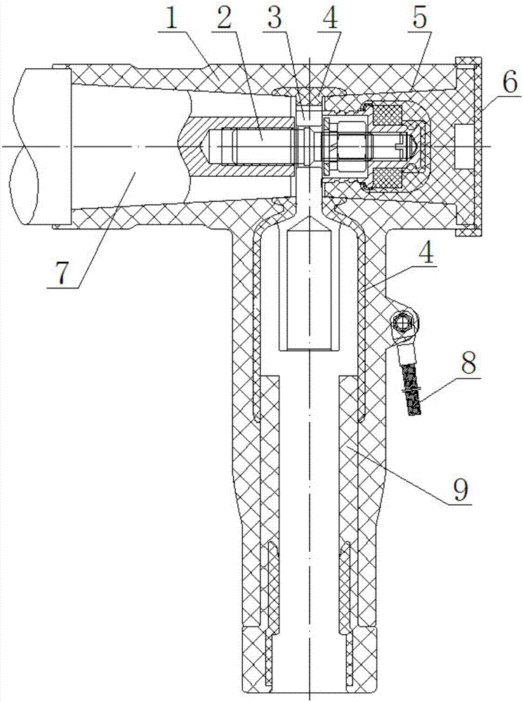
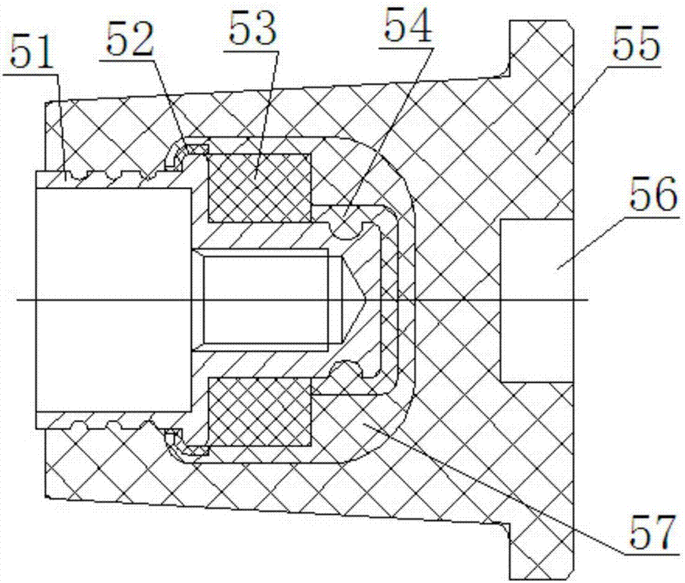
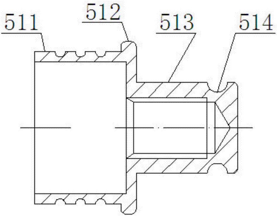
[0022] Such as figure 1 The detachable connector shown for a smart grid monitoring system mainly includes a plug body 1, a connection fitting 2 and a plugging cover 5. The plug body 1 is a hollow cavity with a T-shaped structure and is located in the inner cavity of the plug body 1. A terminal 3, an inner shield 4, a cover 5, and a stress body 9 are arranged in the middle, and a ground wire 8 is connected to the outside of the plug body 1. The connecting fitting 2 is a screw with a double-threaded structure, the inner shield 4 is made of semi-conductive material, and the tail of the inner s...
PUM
 Abstract
Description
Claims
Application Information