A charging and discharging control system for a power source device

A charge-discharge control, power source technology, applied in circuit devices, battery circuit devices, current collectors, etc., can solve the problems of inability to output multiple voltages at the same time, single output voltage, affecting the stability of the output voltage of the battery pack, etc. The effect of intelligent control and all-round protection, high safety index and strong applicability

Active Publication Date: 2020-04-21
HUIZHOU BLUEWAY ELECTRONICS
View PDF6 Cites 0 Cited by
  • Summary
  • Abstract
  • Description
  • Claims
  • Application Information

AI Technical Summary

Problems solved by technology

[0003] In the process of the mobile power source device supplying power to mobile electrical equipment, due to the connection mode of series, parallel or series-parallel connection of multiple single cells in the battery pack, there is a phenomenon of excessive charging or excessive discharge of individual single cells, resulting in The voltage imbalance between single cells affects the stability of the output voltage of the entire battery pack and affects the service life of the battery pack
[0004] The current mobile power system is mostly a platform with a low output voltage, which can no longer meet the needs of some mobile electrical equipment with medium and high voltage, and the output voltage is single, that is, a power system can only output one type of voltage, and cannot output voltage values ​​at the same time Different multi-channel voltages, but users sometimes need to supply power for mobile electrical equipment with different voltage requirements, so they need to replace different mobile power source devices, which brings great inconvenience to users

Method used


Image

  • A charging and discharging control system for a power source device
  • A charging and discharging control system for a power source device
  • A charging and discharging control system for a power source device

Examples


Embodiment Construction

[0038] The implementation mode of the present invention will be explained in detail below in conjunction with the accompanying drawings. The examples given are only for the purpose of illustration and should not be understood as limiting the present invention. The selection of components and accompanying drawings are only preferred embodiments and do not constitute The scope of the patent protection of the present invention is limited, because many changes can be made to the present invention without departing from the spirit and scope of the present invention.

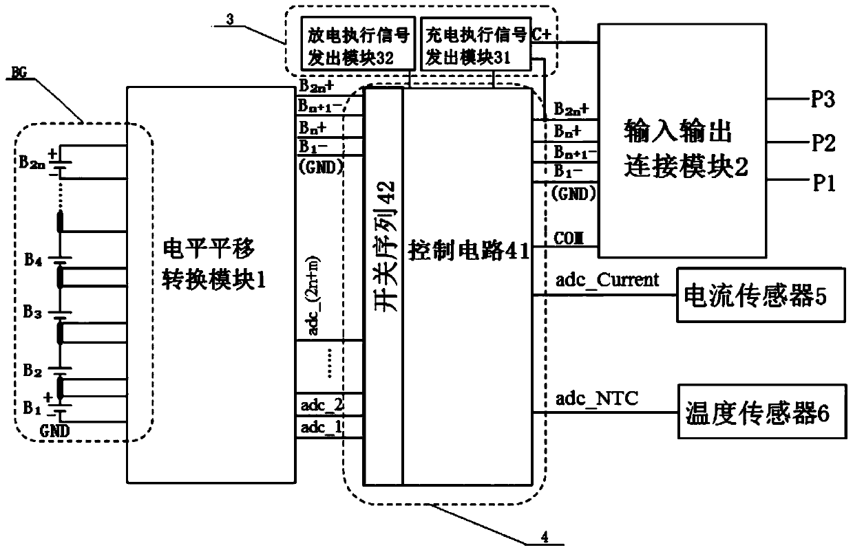
[0039] see figure 1 , is a module structure diagram of a charging and discharging control system for a dual-voltage power source device provided by an embodiment of the present invention. In this embodiment, the charging and discharging control system of a power source device is provided with a battery pack BG and a level shift conversion module 1 connected thereto, an input / output connection module 2, and an executio...


PUM


Abstract

The invention relates to the technical field of portable power supplies, and particularly discloses a charge and discharge control system of a power source device. The charge and discharge control system is provided with a battery pack and a level translational transformation module which is connected with the battery pack. The charge and discharge control system is also provided with an input and output connection module, a performing signal transmitting module and a master control module. The beneficial effects of application of the charge and discharge control system of the power source device are that the analog acquisition input port multiplexing technology is adopted in the master control module, the whole system is enabled to detect more analog quantity through switch sequences and the voltage of each single battery can be detected in real time so that power consumption from the intermediate battery of the series connected single batteries can be transformed to power consumption from total positive power and electric leakage balance of all the single batteries can be realized; and the input and output connection module can at least output two paths of standard discharge voltage of different voltage values so as to meet the requirements of the user for using one power source device to supply power to mobile electrical equipment of different voltage demands.

Description

technical field [0001] The invention relates to the technical field of mobile power sources, in particular to a charging and discharging control system for a power source device. Background technique [0002] In the power system where the mobile power source device is located, considering the platformization of the system, transportation safety and transportation costs, etc., it is required that the output voltage provided by the battery pack in the mobile power source device can be stably and continuously output for power supply. Mobile electrical equipment is connected and used, and the output voltage is required to be neither too high nor too low. [0003] In the process of the mobile power source device supplying power to mobile electrical equipment, due to the connection mode of series, parallel or series-parallel connection of multiple single cells in the battery pack, there is a phenomenon of excessive charging or excessive discharge of individual single cells, result...

Claims


Application Information

Patent Timeline
Patent Type & Authority Patents(China)
IPC IPC(8): H02J7/00
CPCH02J7/0014
Inventor 黄胜高李润朝
Owner HUIZHOU BLUEWAY ELECTRONICS
Why Eureka
Try Eureka