A rear sidewall retreat type deflecting nose sill

A side wall and nose sill technology, applied in the field of sills, can solve problems such as large swells on the opposite bank, increase project cost and construction period, and endanger the safety of the opposite bank, so as to reduce erosion and ensure the safety of the river bank.

Active Publication Date: 2019-08-20
SICHUAN UNIV
View PDF5 Cites 1 Cited by
  • Summary
  • Abstract
  • Description
  • Claims
  • Application Information

AI Technical Summary

Problems solved by technology

However, for a narrow and curved river, the entry point of the water near the downstream side of the river is very easy to approach the opposite bank, and because of the angle between the entry direction and the river, the water will hit the opposite bank at a higher speed, resulting in Larger swells endanger the safety of the opposite bank
For this problem, the existing solutions are usually to widen the downstream channel and strengthen the opposite bank slope, which will increase the project cost and construction period

Method used


Image

  • A rear sidewall retreat type deflecting nose sill
  • A rear sidewall retreat type deflecting nose sill
  • A rear sidewall retreat type deflecting nose sill

Examples


Embodiment 1

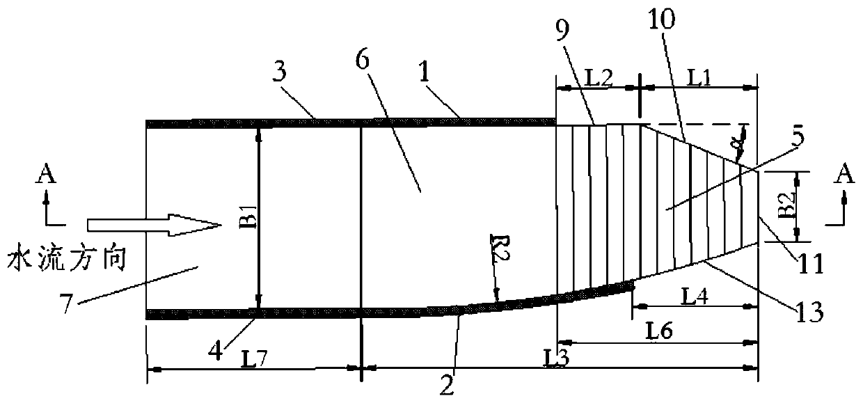
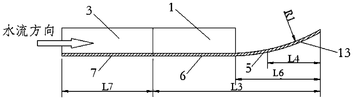
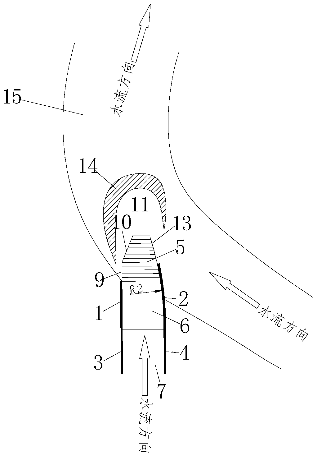
[0023] There is a sharp turn in a certain river, and the outlet of the spillway is just at the turn of the river. According to the conditions of the river, the rear side wall retreating type deflecting nose sill shown in this embodiment is arranged at the sharp bend. The structure of the deflecting nose sill is as follows figure 1 , figure 2 As shown, the relationship with the arrangement position of the river is as follows image 3 shown.

[0024] like figure 1 , figure 2 As shown, in this embodiment, the rear sidewall retreat type deflecting flow nose sill is composed of a transition section connected with the downstream end of the spillway and a deflector section connected with the transition section at one end and connected with the river channel at the other end. The transition section It is composed of the transition section bottom plate 7 and the left wall 3 and the right wall 4 on both sides of the transition section bottom plate. The width of the transition sec...

Embodiment 2

[0028] The outlet of the spillway in a certain river section corresponds to the relatively wide upstream section of the river turn. According to the conditions of the river section, the tail side wall and the retreat-style deflecting nose sill described in this embodiment are arranged at the relatively wide upstream section of the turn to connect the spillway and the river. The structure of the protruding nose ridge is as follows Figure 4 , Figure 5 As shown, the relationship with the arrangement position of the river is as follows Image 6 shown.

[0029] like Figure 4 , Figure 5 As shown, in this embodiment, the rear sidewall retreat type deflecting flow nose sill is composed of a transition section connected with the downstream end of the spillway and a deflector section connected with the transition section at one end and connected with the river channel at the other end. The transition section It is composed of the transition section bottom plate 7 and the left wa...


PUM


Abstract

Disclosed is a tail side wall retreat type flip bucket. The tails ide wall retreat type flip bucket is composed of a transition section and a flip bucket section, wherein the transition section is connected with the downstream tail end of a spillway, one end of the flip bucket section is connected with the transition section, and the other end of the flip bucket section is connected with a riverway. The transition section is composed of a transmission section bottom plate and side walls of the two sides of the transition section bottom plate. The width of the transmission section bottom plate is the same with the width a spillway bottom plate. The flip bucket section is composed of a flip bucket section bottom plate and side walls of the two sides of the flip bucket section bottom plate. The flip bucket section bottom plate is an upwards-concave curved surface or is formed by connecting a plane section located at the same elevation with the transmission bottom plate with an upwards-concave curved surface section in the water flow direction in sequence. A water outlet of the tail of the flip bucket section is formed by combining a side water outlet formed by retreat of tail side wall of the two sides or one side of the flip bucket section, an inclined cutting water outlet and a tail end water outlet. The flip bucket is used for a narrow and curved riverway, scour of a single-side flip jet water flow on the opposite bank of the riverway is weaken, scour on surge of a river bank of the opposite bank is reduced, and the safety of the bank is ensured.

Description

technical field [0001] The invention belongs to the field of ridges in deflecting flow energy dissipation facilities of water conservancy projects, and in particular relates to a side wall retreating type ridge. Background technique [0002] The deflected flow energy dissipation is a form of energy dissipation widely used in water conservancy projects. Most of the discharge structures with an operating water head exceeding 70m adopt deflected flow energy dissipation. The working method of deflecting flow energy dissipation is to introduce the water flow into the discharge channel, then lift the water flow away from the hydraulic structure through the nose sill, and use the kinetic energy of the water flow and the guiding function of the nose sill to throw the water flow into the air and fall into the downstream. The biggest advantage of deflected flow energy dissipation is that the engineering structure is simple, easy to build, and the cost is relatively low. There are var...

Claims


Application Information

Patent Timeline
Patent Type & Authority Patents(China)
IPC IPC(8): E02B8/06
Inventor 张建民许唯临李昕刘善均邓军王韦田忠张法星
Owner SICHUAN UNIV
Why Eureka
Try Eureka