Three-dimensional inertia gas-solid separation flue

A technology of gas-solid separation and flue, which is applied in the field of flue gas dust removal, can solve the problems of increasing the workload of dust removal, and achieve the effect of effective separation

Active Publication Date: 2018-01-26
BEIJING JINGCHENGKELIN ENVIRONMENTAL PROTECTION TECH +1
View PDF10 Cites 0 Cited by
  • Summary
  • Abstract
  • Description
  • Claims
  • Application Information

AI Technical Summary

Problems solved by technology

The current general practice is to replace the flue regularly and increase the follow-up dust removal workload

Method used


Image

  • Three-dimensional inertia gas-solid separation flue
  • Three-dimensional inertia gas-solid separation flue
  • Three-dimensional inertia gas-solid separation flue

Examples


Embodiment Construction

[0028] It should be noted that, in the case of no conflict, the embodiments in the present application and the features in the embodiments can be combined with each other. The present invention will be described in detail below with reference to the accompanying drawings and examples.

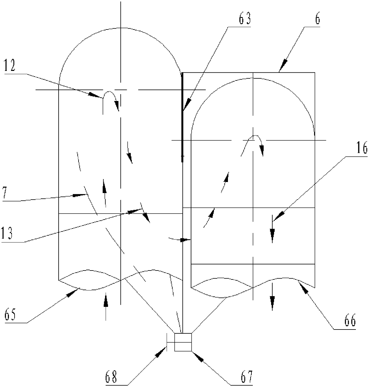
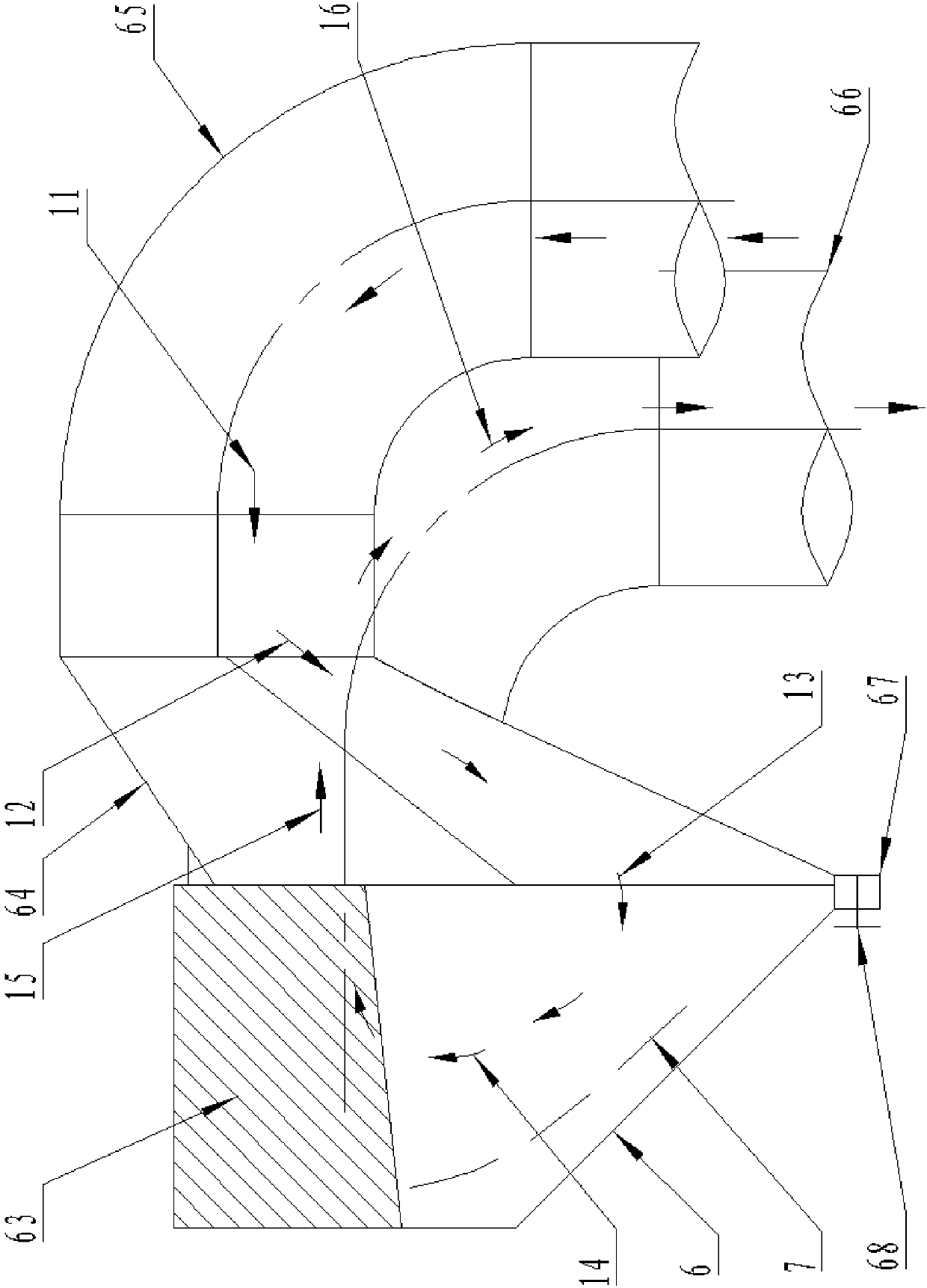
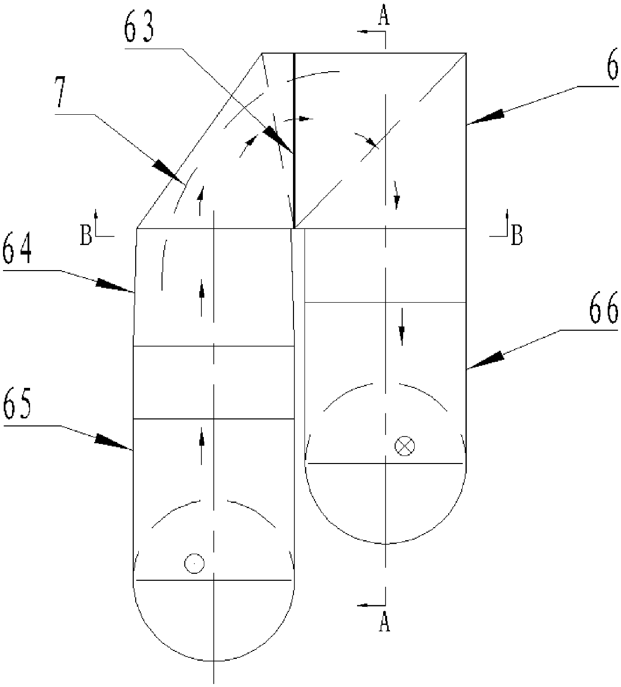
[0029] A three-dimensional inertial gas-solid separation flue, including a hollow shell 6, a closed cavity is arranged in the hollow shell 6, a cavity inlet 61 and a cavity outlet 62 are arranged on the hollow shell 6, and a baffle plate is arranged in the cavity 63, the baffle plate 63 is located between the cavity inlet 61 and the cavity outlet 62, and the hollow shell 6 is provided with a drainage flue 64, and the outlet of the drainage flue 64 is connected to the cavity inlet 61 in a sealed manner, and the drainage flue 64 can guide The flue gas entering the draft flue 64 moves down and enters the cavity, and the baffle plate 63 can make the smoke entering the cavity only flow through the b...


PUM


Abstract

The invention discloses a three-dimensional inertia gas-solid separation flue. The three-dimensional inertia gas-solid separation flue comprises an empty shell (6), a closed cavity is arranged in theempty shell (6), a cavity inlet (61) and a cavity outlet (62) ate formed in the empty shell (6), a shielding plate (63) is arranged in the cavity and is located between the cavity inlet (61) and the cavity outlet (62), a drainage flue (64) is arranged outside the empty shell (6), an outlet of the drainage flue (64) is correspondingly connected with the cavity inlet (61), the drainage flue (64) canguide smoke entering the drainage flue (64) to move downwards and enter the cavity, and the shielding plate (63) can allow smoke entering the cavity to flow through the lower portion of the shieldingplate (63) only. Through the structural design of the three-dimensional inertia gas-solid separation flue, the mature centrifugal separation technology is sufficiently used, and dust in the smoke iscollected.

Description

technical field [0001] The invention relates to the technical field of flue gas dust removal, in particular to a three-dimensional inertial gas-solid separation flue. Background technique [0002] At present, in the flue gas dedusting system, natural sedimentation and centrifugal separation technology are widely used. Its advantages are mature technology, large processing flow, strong high temperature adaptability, small resistance, and less maintenance work, but there are also problems such as large particle size, secondary Weaknesses such as high dust emission and limited separation efficiency. A large amount of high-temperature flue gas and dust will be generated during converter steelmaking, which will be introduced into the dust removal system after being cooled by the flue. The high-temperature flue gas and dust of converter steelmaking have great value, but factors such as the combustion and explosion characteristics of flue gas and the high-temperature wear of dust ...

Claims


Application Information

Patent Timeline
Patent Type & Authority Applications(China)
IPC IPC(8): F27D17/00B01D45/12B01D45/02
Inventor 杨源满井小海杨明华王林
Owner BEIJING JINGCHENGKELIN ENVIRONMENTAL PROTECTION TECH
Why Eureka
Try Eureka