

One-piece component with active flow control
A flow control and active technology, applied in fluid flow, aircraft control, boundary layer control, etc., can solve problems such as laminar flow and delay
- Summary
- Abstract
- Description
- Claims
- Application Information
AI Technical Summary
Problems solved by technology
Method used
Image

Examples
Embodiment Construction
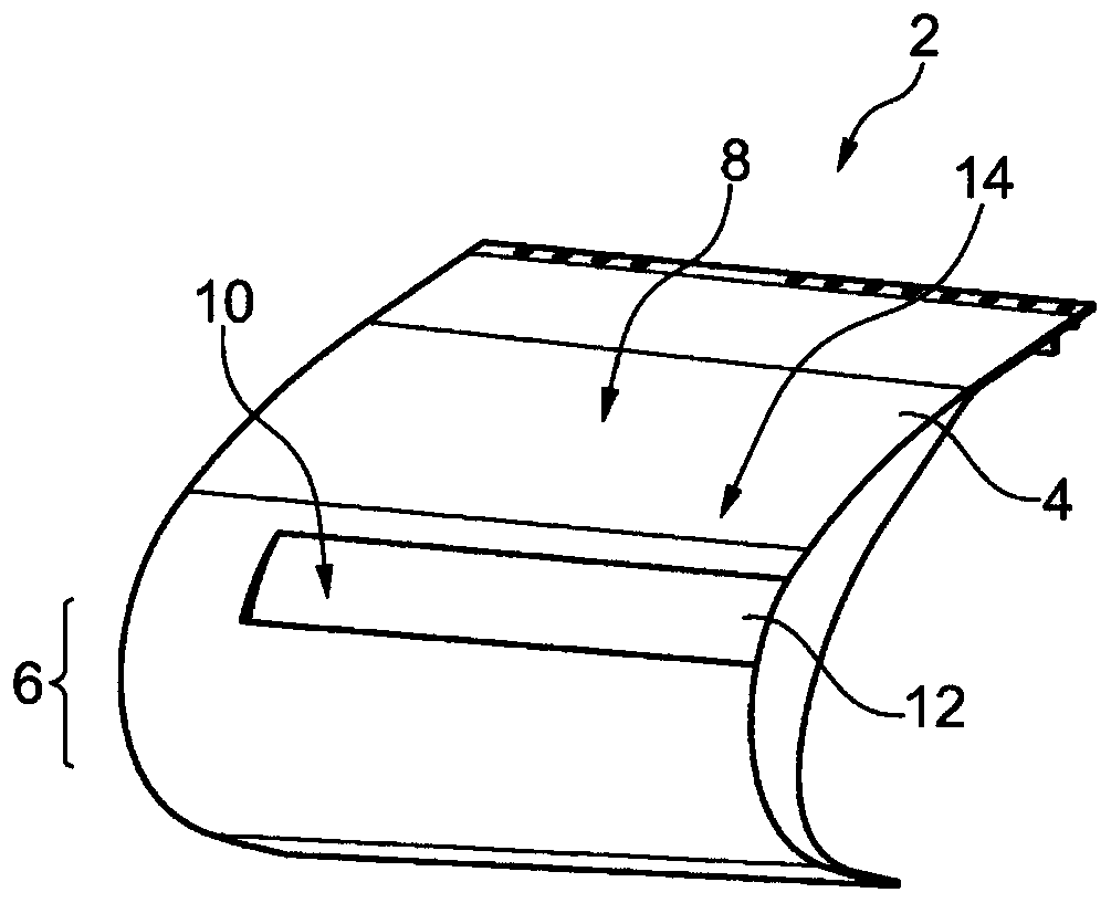
[0036] figure 1 Shown is a part of a flow profile 2 having a flat skin section 4 which is bent to form a circular leading edge region 6 designed as Used to highlight into the flow. The outer side 8 of the skin section 4 comprises a depression 12 terminating in a slit 10, wherein the depth of said depression increases towards the slit 10 from a base area 14 which is in contact with the skin section. The slits 10 on the 4 are spaced apart. For example, the flow pattern body 2 can be arranged on the leading edge of the wing or on the empennage unit such that the outer side 8 of the flow pattern body 2 is exposed to the flow and forms a flow boundary layer on the flow pattern body 2 . The high-energy gas flow can be blown into or drawn out of the boundary layer via the slit 10 , so that the flow around the flow pattern 2 is influenced and in particular the generation of turbulence is delayed.
[0037] The following figures clearly show that the flow pattern body 2 is produced b...
PUM
 Abstract
Description
Claims
Application Information