Laser marking machine and method of adjusting distance between scanning head and marking object and automatic focusing method of marking machine

A laser marking machine and laser marking technology, applied in the field of laser marking, can solve the problems of reducing marking accuracy and speed, and achieve the effect of increasing marking speed and ensuring accuracy

Active Publication Date: 2018-03-06
GUANGZHOU NEW CKLASER CO LTD
View PDF6 Cites 11 Cited by
  • Summary
  • Abstract
  • Description
  • Claims
  • Application Information

AI Technical Summary

Problems solved by technology

[0004] The invention provides a laser marking machine, a method for adjusting the distance between the scanning head of the laser marking machine and the marking object, and an automatic focusing method for the marking machine. The problem of marking accuracy and speed

Method used


Image

  • Laser marking machine and method of adjusting distance between scanning head and marking object and automatic focusing method of marking machine
  • Laser marking machine and method of adjusting distance between scanning head and marking object and automatic focusing method of marking machine
  • Laser marking machine and method of adjusting distance between scanning head and marking object and automatic focusing method of marking machine

Examples


Embodiment 1

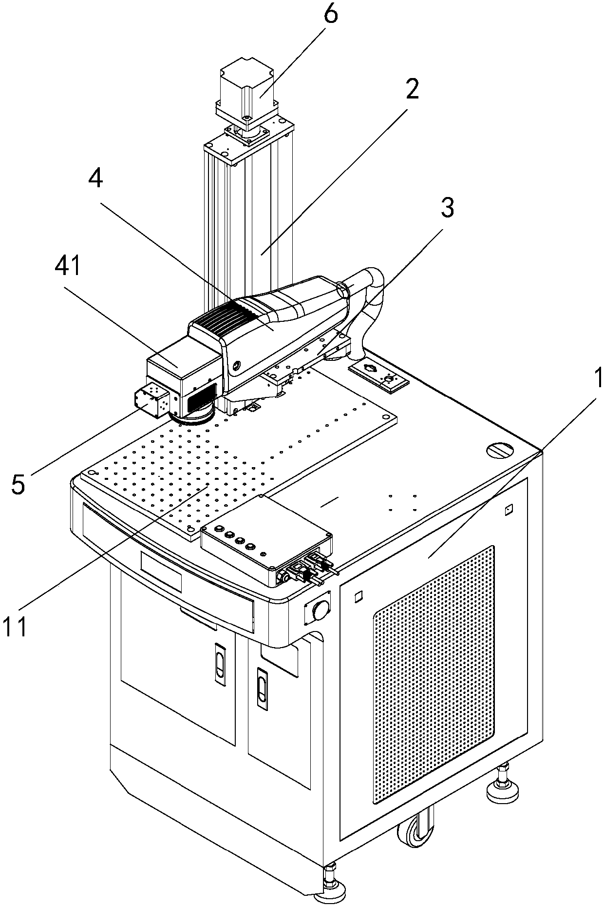
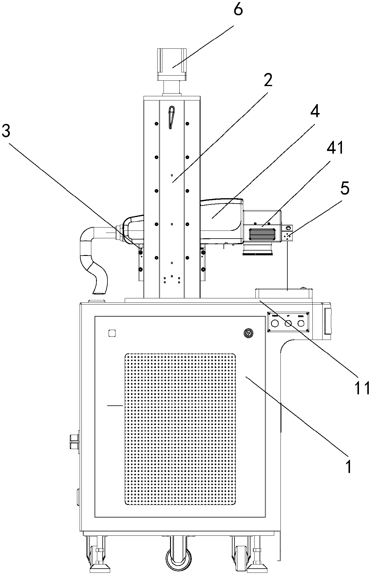
[0024] A laser marking machine, such as figure 1 and figure 2 As shown, a base 1 is included, and a frame 2 is arranged on the base 1. A vertically extending guide rail is provided on the frame 2. A pallet 3 is arranged on the guide rail, and the pallet 3 can slide along the guide rail. A laser marking assembly 4 is arranged on the pallet 3 , the laser marking assembly 4 is used to generate marking laser, and the marking laser is emitted from the scanning head 41 .

[0025] The scanning head includes an X mirror and a Y mirror installed in sequence. The X mirror is installed on the rotation output shaft of the X motor, and the Y mirror is installed on the rotation output shaft of the Y motor. The direction of the rotation axis of the X motor is the same as that of the Y motor. The directions of the rotation axes are perpendicular to each other, and the marking laser is shot onto the X mirror and the Y mirror in turn. After the X mirror and the Y mirror change direction, the ...

Embodiment 2

[0033] The difference between this embodiment and embodiment 1 mainly lies in the second drive assembly. Specifically:

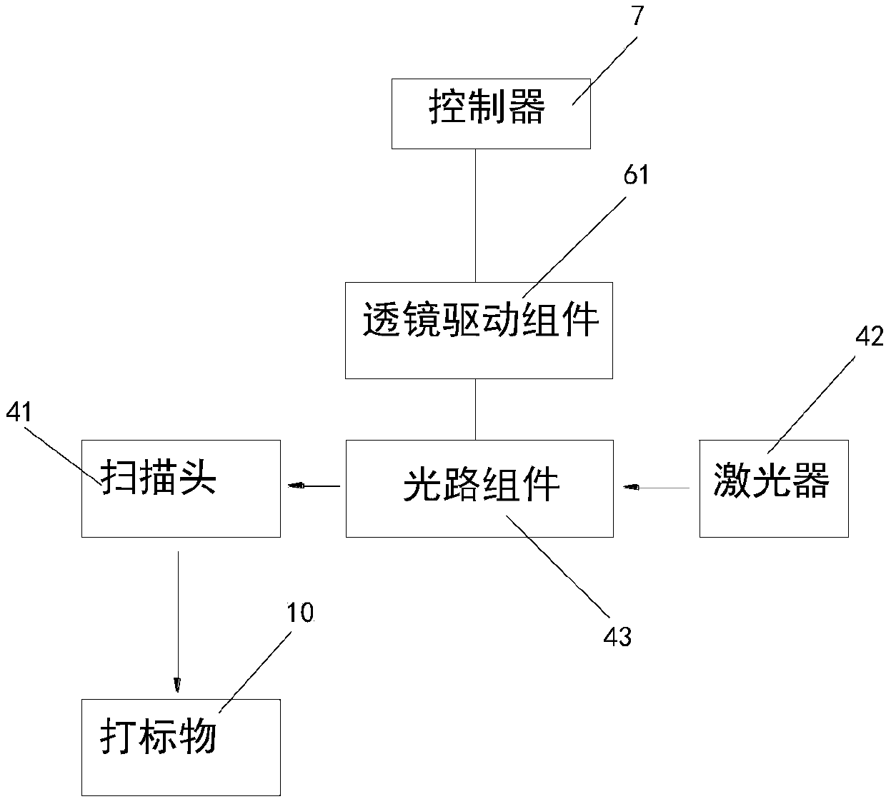
[0034] Laser marking machine, including a base and a marking machine table for placing marking objects on the base, the marking machine table can move up and down, the frame above the marking machine table, the support table set on the frame, the support table A laser marking component is set on the table, and the laser marking component includes a laser, an optical path assembly and a scanning head installed in sequence. The optical path assembly includes several concave lenses and / or convex lenses, located between the laser and the scanning head, for adjusting the beam of the incident laser The focal length, the marking laser exits from the laser, passes through the optical path assembly, and enters the scanning head. The scanning head includes several reflective lenses, which are used to change the direction of the marking laser, so that the marking laser...

Embodiment 3

[0038] This implementation is improved on the basis of Embodiment 1 or 2, and this embodiment illustrates a solution for a laser marking machine for three-dimensional marking objects.

[0039] like Image 6 As shown, when specifically marking the marking object 10, the laser marking machine can also be connected to an external control terminal. A virtual model of the marking object 10 is established in the control terminal, and the marking pattern is pasted on the surface of the virtual model.

[0040] Because the virtual model of the marking object 10 is stored in the control terminal, and various parameters of the virtual model are also stored, as long as the distance from any point on the model to the distance measuring component 5 is known, the distance from any other point on the virtual model to the distance measuring component 5 can be known. The distance of component 5. Therefore, in this embodiment, a feature point needs to be preset on the surface of the marking ob...


PUM


Abstract

The invention discloses a laser marking machine, a method of adjusting the distance between a scanning head of the laser marking machine and a marking object and an automatic focusing method of the marking machine. The laser marking machine comprises a rack, a supporting table, a controller, a first driving assembly and a distance measuring assembly, wherein the supporting table is arranged on therack and can move up and down along the rack; a laser marking assembly is arranged on the supporting table; the first driving assembly is arranged on the rack and is used for driving the supporting table to move up and down along the rack; the distance measuring assembly is arranged on the laser marking assembly and comprises a laser pointer and a laser sensor; the laser pointer is used for emitting laser to the surface of the marking object; the laser sensor is used for receiving the laser reflected by the surface of the marking object and sending a signal to the controller; the controller calculates the vertical distance from the surface of the marking object to the distance measuring assembly according to the signal; and the first driving assembly is used for driving the supporting table to drive the laser marking assembly to move to the distance between the scanning head and the surface of the marking object according to the signal, thereby achieving the preset distance.

Description

technical field [0001] The invention belongs to the technical field of laser marking, and in particular relates to a laser marking machine, a method for adjusting the distance between a scanning head of the laser marking machine and a marking object, and an automatic focusing method for the marking machine. Background technique [0002] Laser marking machine is an optical, mechanical and electrical integration equipment that combines laser technology and computer technology. At present, the application of laser marking technology in industry at home and abroad is being gradually paid attention to by people. Various new marking equipment emerge in an endless stream. It is replacing the traditional marking method with its unique advantages. It can be used in various mechanical parts, electronic components Print marks on the surface of various objects such as devices, integrated circuit modules, instruments, and meters. [0003] Its working principle is that the laser generate...

Claims


Application Information

Patent Timeline
Patent Type & Authority Applications(China)
IPC IPC(8): B23K26/046B23K26/362B23K26/064
CPCB23K26/082B23K26/361B23K26/702B23K26/048B41J2/435B41J29/393B41M5/24B23K26/046B23K26/0648
Inventor 徐强
Owner GUANGZHOU NEW CKLASER CO LTD
Why Eureka
Try Eureka