LED drive circuit

A technology of LED driving and LED array, applied in the field of driving circuit, can solve the problems of loss, complicated circuit, influence of LED and other transistors, etc., and achieve the effect of simple structure

Inactive Publication Date: 2018-03-23
黄福芝
View PDF0 Cites 0 Cited by
  • Summary
  • Abstract
  • Description
  • Claims
  • Application Information

AI Technical Summary

Problems solved by technology

[0002] When encountering such as thunder and lightning, the start-up of large electrical equipment, etc., the voltage will increase instantaneously, resulting in a sudden change of current, and the LED drive circuit in the prior art often cannot effectively release the sudden change of current, thereby affecting LEDs and other transistors Or even damage, causing losses; usually several LEDs in the LED drive circuit are connected in series, if one of the LEDs is damaged and disconnected after the series connection, it is very troublesome to find out the bad LED, and the LED circuit in the prior art is more complicated and the cost is higher

Method used


Image

  • LED drive circuit

Examples


Embodiment Construction

[0017] The present invention will be further described below in conjunction with the accompanying drawings. The following examples are only used to illustrate the technical solution of the present invention more clearly, but not to limit the protection scope of the present invention.

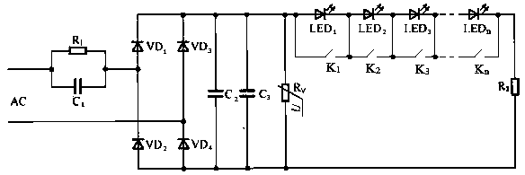
[0018] Such as figure 1 As shown, an LED driving circuit is characterized in that it includes a step-down current limiting circuit, a rectifier circuit, a filter circuit, an LED array, and a piezoresistor R used to protect the LED from instantaneous high voltage breakdown. V ;

[0019] The step-down current limiting circuit includes resistor R1 and capacitor C1, the rectifier circuit includes rectifier diodes VD1, VD2, VD3 and VD4, the filter circuit includes capacitors C2 and C3, and the LED array includes several LEDs and several switch K;

[0020] The R1 and C1 are connected in parallel to form a step-down current-limiting circuit, one end of the step-down current-limiting circuit is conne...


PUM


Abstract

The present invention discloses an LED driver circuit, and the drive circuit is characterized in that the drive circuit comprises a step-down current limiting circuit, a rectifier circuit, a filter circuit, an LED array, and a piezoresistor for protecting an LED from being broken by an instantaneous high voltage. The step-down current limiting circuit comprises a resistor R1 and a capacitor C1. The rectifier circuit comprises rectifier diodes VD1, VD2, VD3 and VD4. The filter circuit comprises capacitors C2 and C3. The LED array comprises a plurality of LEDs and a plurality of switches K. Thedrive circuit is advantageous in that the drive circuit is simple in structure, and has the step-down, current-limiting, rectification and filtering functions; the drive circuit can solve a problem that the sudden increase of a voltage of the circuit affects or damages an element because the circuit is provided with the piezoresistor; the LED is in parallel connection with the switches, so the drive circuit can quickly find out a damaged LED.

Description

technical field [0001] The invention relates to an LED drive circuit and belongs to the technical field of drive circuits. Background technique [0002] When encountering such as thunder and lightning, the start-up of large electrical equipment, etc., the voltage will increase instantaneously, resulting in a sudden change of current, and the LED drive circuit in the prior art often cannot effectively release the sudden change of current, thereby affecting LEDs and other transistors Or even damage, causing losses; usually several LEDs in the LED drive circuit are connected in series, if one of the LEDs is damaged and disconnected after the series connection, it is very troublesome to find out the bad LED, and the LED circuit in the prior art is more complicated and the cost is higher . Contents of the invention [0003] The technical problem to be solved by the present invention is to overcome the defects of the prior art and provide an LED driving circuit. [0004] In or...

Claims


Application Information

Patent Timeline
Patent Type & Authority Applications(China)
IPC IPC(8): H05B33/08H05B44/00
CPCH05B45/00H05B45/50Y02B20/30
Inventor 黄福芝
Owner 黄福芝
Why Eureka
Try Eureka