Concrete-filled steel tube creep testing device considering initial stress of steel tube

A technology of concrete-filled steel pipe and initial stress, which is applied in the direction of applying stable tension/pressure to test the strength of materials, and can solve problems such as stress application of steel pipe concrete structures, difficulty in controlling the balance of test devices, and increased manpower and material resources, making it difficult to manufacture and process Small size, high promotion and application value, and convenient construction

Active Publication Date: 2018-04-06
TAIYUAN UNIV OF TECH
View PDF14 Cites 8 Cited by
  • Summary
  • Abstract
  • Description
  • Claims
  • Application Information

AI Technical Summary

Problems solved by technology

Among them, the counterweight of the lever method mainly uses cables to connect the counterweight and the loading beam. However, for large-sized counterweights, it is difficult to control the balance of the test device when using hoisting equipment to load the counterweights.
The main disadvantage of the spring loading method is that it needs to gradually increase the load over time, which increases a lot of manpower and material resources.
In addition, existing methods are difficult to apply stress to CFST structures subjected to varying loads.

Method used


Image

  • Concrete-filled steel tube creep testing device considering initial stress of steel tube
  • Concrete-filled steel tube creep testing device considering initial stress of steel tube
  • Concrete-filled steel tube creep testing device considering initial stress of steel tube

Examples


Embodiment Construction

[0024] The conception, specific details and obtained technical effects of the present invention will be further described below in conjunction with the accompanying drawings. The lever loading method is loaded by directly placing a counterweight on the upper part of the lever beam, which is convenient for applying large-sized counterweights, and can effectively ensure the lateral stability of the loading device and the constant applied external load. The loading device is simple, and can meet the load of the creep test of the concrete filled steel pipe under the initial stress state.

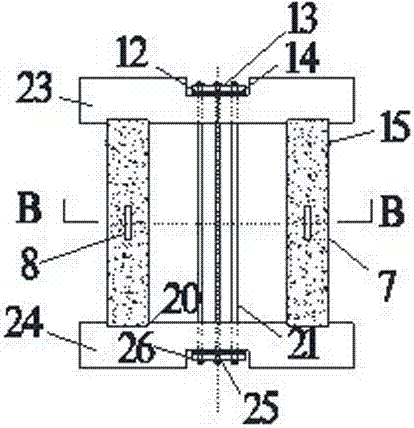
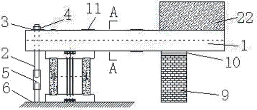
[0025] figure 1 with figure 2 A test device for applying initial stress to a steel pipe according to an embodiment of the present invention is schematically given. figure 1 The initial stress loading device of the steel pipe includes the upper steel plate 23, the lower steel plate 24, the concrete in the pipe 19, the threaded steel bar 21, the steel pipe concrete test block 7, the vibrating w...


PUM


Abstract

The invention belongs to the technical field of concrete-filled steel tube compression resistance and creep tests and in particular relates to a concrete-filled steel tube creep testing device considering initial stress of the steel tube. The concrete-filled steel tube creep testing device comprises a steel tube initial stress loading device and a lever-type concrete creep loading device, whereinthe steel tube initial stress loading device is arranged on a rigid foundation, a concrete-filled steel tube test block provided with a vibration wire strain gauge is arranged in the steel tube initial stress loading device, the steel tube initial stress loading device is arranged at the lower side of the lever-type concrete creep loading device, a structure capable of applying a loading force isarranged at one end of the lever-type concrete creep loading device, and the other end of the lever-type concrete creep loading device is connected with ground by virtue of a structure with length adjustable. The concrete-filled steel tube creep testing device provided by the invention has the advantages that each part is low in manufacturing and processing difficulty, construction is convenient,materials can be directly selected from a construction site, cost is relatively low, and safety and reliability are realized, so that the concrete-filled steel tube creep testing device provided by the invention has relatively great popularization and application value and a relatively good application prospect.

Description

technical field [0001] The invention belongs to the technical field of steel pipe concrete anti-compression creep test, in particular to a steel pipe concrete creep test device considering the initial stress of steel pipes. Background technique [0002] For long-span concrete-filled steel tube stiff-frame arch bridges located in deep mountain and canyon areas such as Guizhou, there are many inconveniences in the construction of stiff-frame arch bridges using traditional support construction methods. Therefore, the cantilever assembly method or stiff-frame method often becomes the first or must select. The construction method is to erect the steel pipe skeleton first, and then pour concrete relying on the stiff skeleton after the skeleton construction is completed, so as to form the steel pipe concrete arch bridge. Before the concrete in the pipe is poured, developed its strength and bears the load, the steel pipe has already begun to bear the load. The previous research re...

Claims


Application Information

Patent Timeline
Patent Type & Authority Applications(China)
IPC IPC(8): G01N3/08G01N3/14
Inventor 王永宝宋帅刘芳苗晨曦
Owner TAIYUAN UNIV OF TECH
Why Eureka
Try Eureka