Antenna system and mobile terminal

An antenna system and antenna unit technology, which is applied in the field of communication, can solve problems such as short wavelength, high frequency of millimeter wave antennas, weakening of the strength of the metal frame of the metal back shell, etc., and achieve the goals of reducing the opening area, improving reliability, and increasing strength Effect

Inactive Publication Date: 2018-04-20
AAC TECH PTE LTD
View PDF6 Cites 15 Cited by
  • Summary
  • Abstract
  • Description
  • Claims
  • Application Information

AI Technical Summary

Problems solved by technology

However, the millimeter-wave antenna has high frequency and short wavelength, and is easily blocked by metal. Therefore, it is necessary to set a large opening on the metal back shell or metal frame, and then place the entire millimeter-wave antenna array in the opening. This large-area The opening of the metal back shell and the metal frame weakens, which affects the reliability of the entire mobile phone

Method used


Image

  • Antenna system and mobile terminal
  • Antenna system and mobile terminal
  • Antenna system and mobile terminal

Examples


Embodiment Construction

[0044] The present invention will be described in further detail below through specific embodiments and in conjunction with the accompanying drawings.

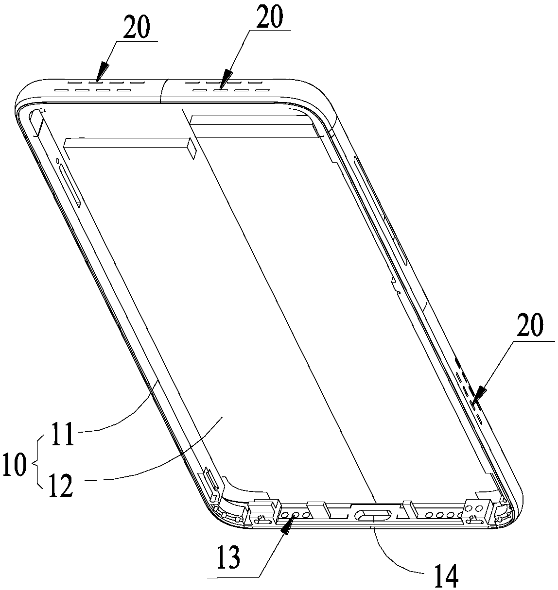
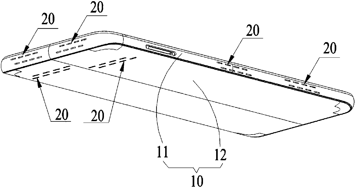
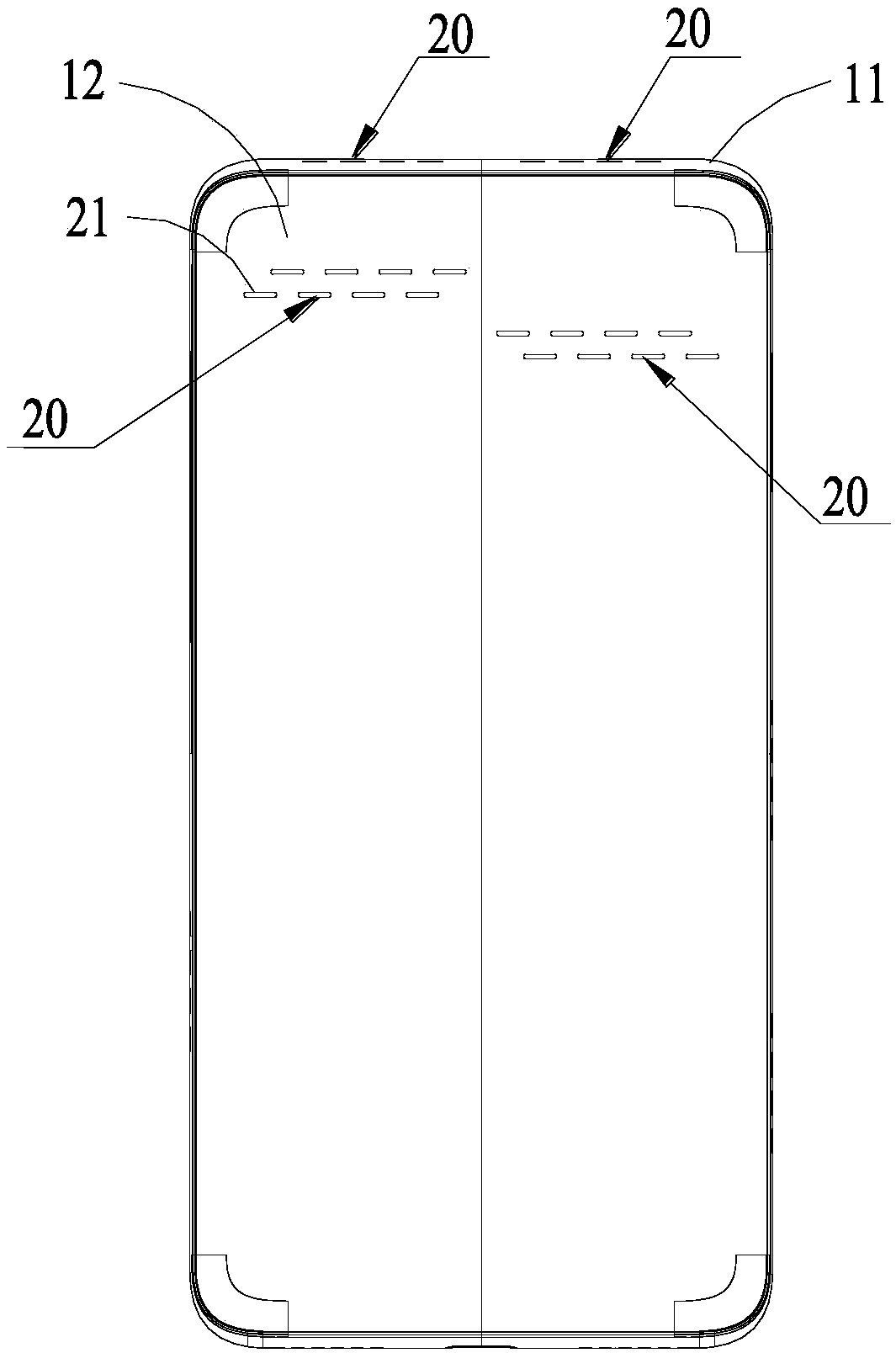
[0045] An embodiment of the present invention provides an antenna system, such as Figure 1-9 As shown, the antenna system includes a housing 10 and at least one set of antenna arrays 20 , and each antenna array 20 includes at least two antenna units 21 . The surface of the housing 10 is provided with a plurality of cavities, each cavity is filled with a dielectric material 30 to form the antenna unit 20, as Figure 8-9 As shown, each cavity is filled with a dielectric material 30, such a cavity and the dielectric material 30 filled in it together form an antenna unit 21, and each antenna array 20 includes two, three or more The opening directions of the concave cavities are parallel, so that these concave cavities and the dielectric material 30 filled in them form a millimeter wave array antenna, that is, a plurality of ante...


PUM


Abstract

The invention relates to the technical field of communication, and especially relates to an antenna system and a mobile terminal. The antenna system comprises a housing and at least one antenna array,wherein each antenna array comprises at least two antenna units. The surface of the housing is provided with cavities, and the interior of each cavity is provided with a dielectric material, so as toform an antenna unit. The opening directions of the cavities are parallel, so as to form a millimeter wave array antenna. According to the invention, the housing is directly provided with antenna units, i.e., arranging the cavities on the housing to form the millimeter wave array antenna. Compared with the prior art where a bigger opening is set for placing the whole millimeter wave array antenna, the antenna can remarkably reduce the opening area of the housing, and the cavities are set at intervals, i.e., still setting connection parts between the cavities. Therefore, the strength of the whole housing can be improved, and the reliability of the whole antenna system can be improved.

Description

technical field [0001] The present invention relates to the technical field of communication, in particular to an antenna system and a mobile terminal. Background technique [0002] As the world's standardization bodies set out to define the next generation of wireless networks, the vision of 5G is forcing researchers to change the way they think. The spectral efficiency of 4G networks is not sufficient to provide faster data transfer rates, low latency, and high capacity. Therefore, there is a need for wireless networks that can provide ubiquitous, instantaneous mobile broadband data. The data rate is directly related to the available spectrum. According to Shannon's theorem, the capacity is a function of bandwidth (that is, spectrum) and channel noise. The spectrum below 6GHz has been allocated, and the spectrum above 6GHz, especially the frequency of millimeter waves, has become The key frequency band for 5G communication. [0003] In the prior art, the metal frame and ...

Claims


Application Information

Patent Timeline
Patent Type & Authority Applications(China)
IPC IPC(8): H01Q1/24H01Q21/29
CPCH01Q1/242H01Q21/293
Inventor 刘见传岳月华
Owner AAC TECH PTE LTD
Why Eureka
Try Eureka