Aquatic feed mixing device for microptenus salmoides

A kind of aquatic feed and mixing device technology, which is applied in the direction of feed, mixer, mixer with rotating stirring device, etc., can solve the problems of increasing processing cost, unsaturated working time of workers, single function, etc., and achieve stable performance improvement and improvement Practical performance, scientific and reasonable structure

Inactive Publication Date: 2018-05-04
ZHANJIANG YUHAO BIOLOGICAL TECH CO LTD
View PDF4 Cites 1 Cited by
  • Summary
  • Abstract
  • Description
  • Claims
  • Application Information

AI Technical Summary

Problems solved by technology

[0003] However, the mixing equipment currently on the market has a complex structure and a single function. In the process of mixing aquatic feed, after the aquatic feed is mixed, it is necessary to transfer the mixed mixed feed to the screening equipment for screening. The process is not only time-consuming and labor-intensive, but also the working time of the workers in the two processes is not saturated, resulting in a waste of human resources and increasing the processing cost; due to the large volume and heavy weight of the mixing equipment, in order to facilitate movement, the bottom of the mixing equipment is installed. However, since the structure of the universal wheel cannot meet the stability required by the mixing equipment during normal operation, the mixing equipment is prone to shaking or even moving during normal operation. When the mixing equipment is receiving materials, the receiving box often occurs The operator cannot replace the receiving box in time after it is full, which leads to the problem that the aquatic feed is spilled on the ground, and the operator needs to clean it, which is time-consuming and laborious

Method used


Image

  • Aquatic feed mixing device for microptenus salmoides
  • Aquatic feed mixing device for microptenus salmoides
  • Aquatic feed mixing device for microptenus salmoides

Examples


Embodiment

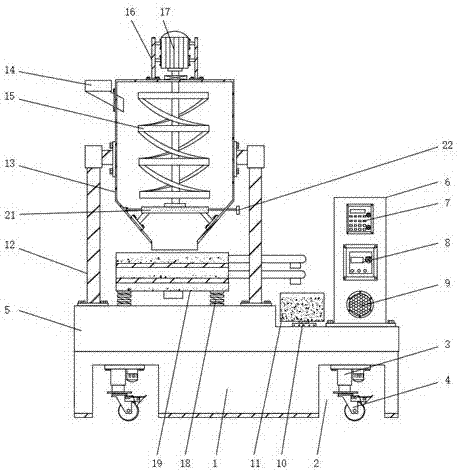
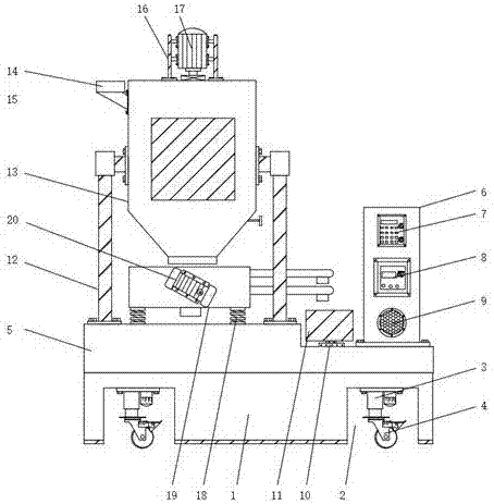
[0026] Example: such as Figure 1-5 As shown, the present invention provides a technical solution, an aquatic feed mixing device for California perch, comprising a support base 1, a groove 2 is provided on the lower surface of the support base 1, and an electro-hydraulic rod is fixedly installed on the inner top of the groove 2 3. A universal wheel 4 is fixedly installed on the lower end of the electro-hydraulic rod 3, a pressure bearing plate 5 is fixedly installed on the upper surface of the support seat 1, an electric control box 6 is fixedly installed on the upper surface of the pressure bearing plate 5, and the pressure bearing plate 5 A control switch 7 is fixedly installed on the front surface, and a MAM-100 controller 8 is fixedly installed on the front surface of the pressure bearing plate 5 close to the lower end of the control switch 7, and the front surface of the pressure bearing plate 5 is close to the MAM-100 controller 8. A buzzer 9 is fixedly installed at the ...


PUM


Abstract

The invention discloses an aquatic feed mixing device for microptenus salmoides. The aquatic feed mixing device for the microptenus salmoides comprises a supporting seat; an electric hydraulic rod isfixedly mounted at the top end of the interior of a groove; a pressure sensor is fixedly mounted in the position, close to one side of an electric control box, of the upper surface of a pressure bearing plate; a mixing barrel is fixedly mounted at the top of the supporting rod; a feeding trough is mounted on one side of the top of the mixing barrel in an embedded manner; the upper end of a dampingspring is fixedly connected with a screening box; a vibrating motor is fixedly mounted on the front surface of the screening box. According to the aquatic feed mixing device for microptenus salmoides, mixed aquatic feed can be screened through the screening box and the vibrating motor; the stability of the mixing device in normal work is further improved on the premise of not influencing the normal movement of the mixing device; through the pressure sensor, a controller and a buzzer, the buzzer can make a sound when a material receiving box is approximately full, so that an operator can replace the material receiving box conveniently in time.

Description

technical field [0001] The invention relates to the technical field of mixing equipment, in particular to an aquatic feed mixing device for California perch. Background technique [0002] Mixing equipment is a mechanical equipment that uses mechanical force and gravity to uniformly mix two or more materials. During the mixing process, it can also increase the contact surface area of ​​the materials to promote chemical reactions; it can also accelerate physical changes. [0003] However, the mixing equipment currently on the market has a complex structure and a single function. In the process of mixing aquatic feed, after the aquatic feed is mixed, it is necessary to transfer the mixed mixed feed to the screening equipment for screening. The process is not only time-consuming and labor-intensive, but also the working time of the workers in the two processes is not saturated, resulting in a waste of human resources and increasing the processing cost; due to the large volume an...

Claims


Application Information

Patent Timeline
Patent Type & Authority Applications(China)
IPC IPC(8): B01F7/16B01F15/02B01F3/22A23N17/00B07B1/28B07B1/42B07B1/46B01F23/80
CPCA23N17/007B07B1/28B07B1/42B07B1/4663B07B2201/04B01F23/80B01F27/80B01F33/501B01F35/754B01F2101/18
Inventor 张皓哲任童任可张嘉强
Owner ZHANJIANG YUHAO BIOLOGICAL TECH CO LTD
Why Eureka
Try Eureka