Laser spot welder for battery

A laser spot welding and battery technology, applied in laser welding equipment, welding equipment, metal processing equipment, etc., can solve the problems of low welding efficiency, achieve the effect of improving welding efficiency, solving low welding efficiency and improving welding accuracy

Pending Publication Date: 2018-06-12
HUIZHOU DESAY AUTOMATION TECH
View PDF0 Cites 7 Cited by
  • Summary
  • Abstract
  • Description
  • Claims
  • Application Information

AI Technical Summary

Problems solved by technology

[0004] Aiming at the deficiencies of the prior art, the present invention provides a battery laser spot welder, which can automatically perform batch welding on the positive electrode of the cell module to be welded, thereby solving the problem of low welding efficiency in the prior art

Method used


Image

  • Laser spot welder for battery
  • Laser spot welder for battery
  • Laser spot welder for battery

Examples


Embodiment 1

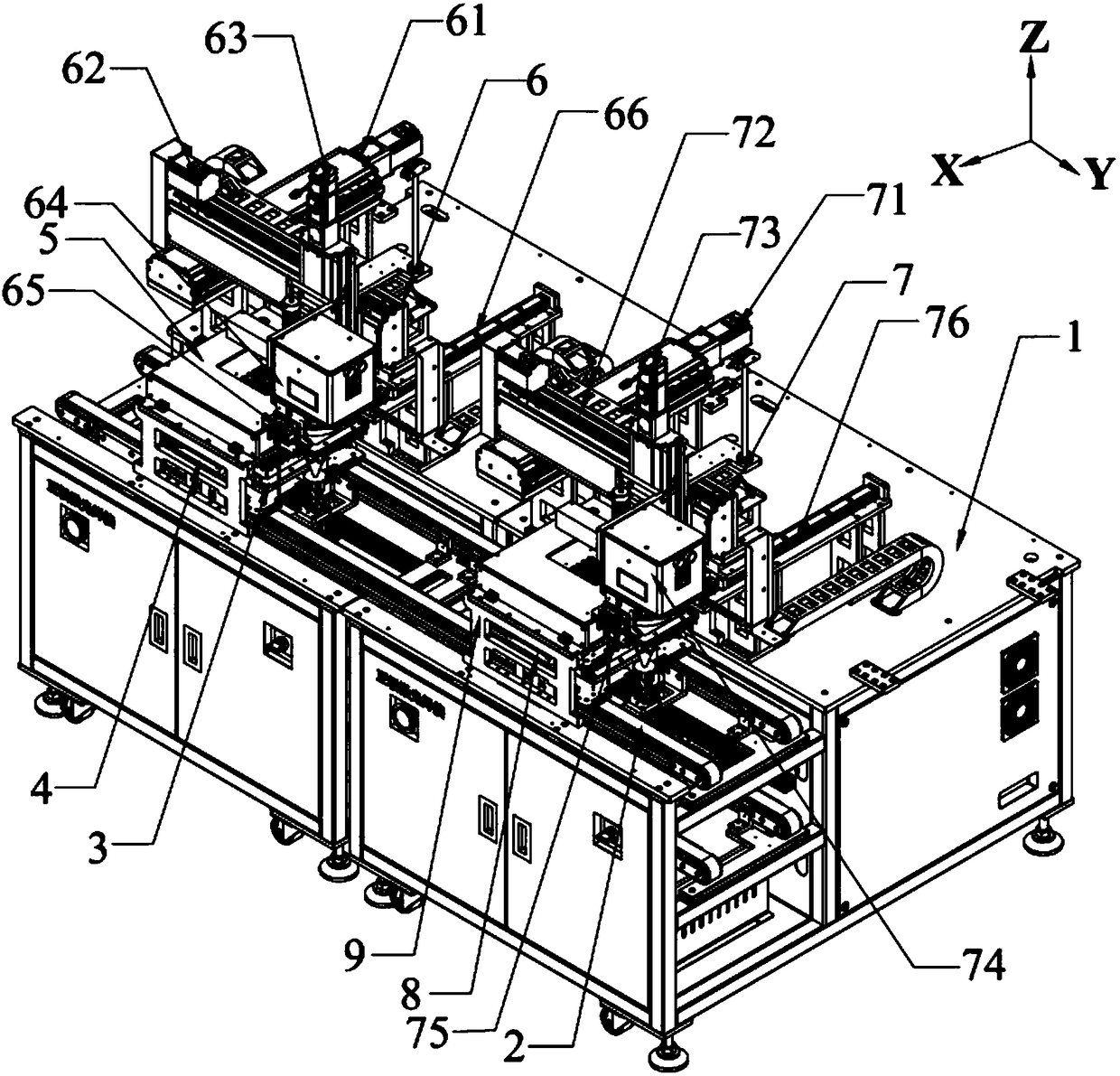
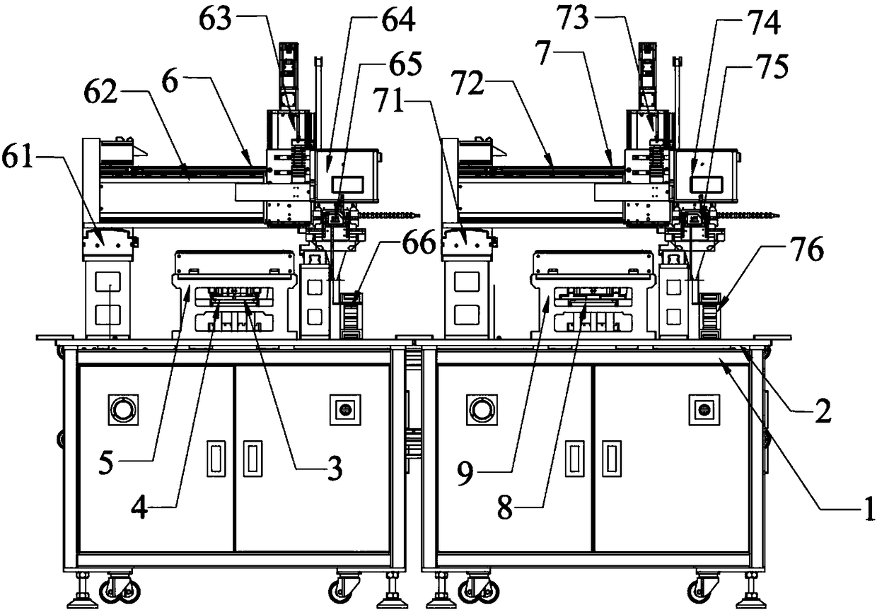
[0055] In this embodiment, the battery laser spot welding machine includes one welding station as an example. Please refer to figure 1 and 2 , respectively showing the three-dimensional structure diagram and the front view structure diagram of the battery laser spot welding machine. The structure of the battery laser spot welding machine provided by the present embodiment includes: a frame 1, a transmission line 2, a plurality of carriers 3 and the first welding station; the first welding station includes: the first spot welding mechanism 6 and The first stop piece.

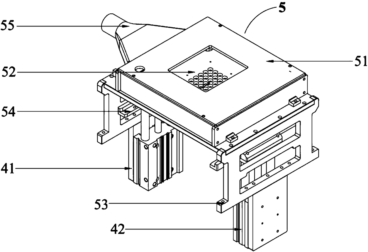
[0056]The transmission line 2 is set on the frame 1, the transmission line 2 has a conveying line and a return line, the conveying line is used to transport the carrier 3 on which the battery module is to be welded, and the return line is used to recover the empty carrier; the carrier 3 There are a plurality of them, which are arranged at equal intervals on the transmission line 2. Specifically, the carrier 3 ...

Embodiment 2

[0063] This embodiment provides a battery laser spot welding machine with another structure. The battery laser spot welding machine in this embodiment is different from Embodiment 1 in that it includes two welding stations, which are the first welding station and the second welding station, and the two welding stations are arranged on the transmission line 2 according to the process. on the same side. Of course, the two welding stations can also be located on opposite sides of the transmission line 2 .

[0064] review figure 1 and 2 , The second welding station includes: the second spot welding mechanism 7, the second stopper, the second jacking assembly 8 and the second positioning mechanism 9 with the same function as the first embodiment. The second spot welding mechanism 7 , the second stopper, the second jacking assembly 8 and the second positioning mechanism 9 adopt the same operation principle as that of the first embodiment to realize positive electrode welding of t...


PUM


Abstract

The invention discloses a laser spot welder for a battery. The laser spot welder comprises a machine frame, a conveying line, multiple carriers and at least one welding station, wherein the conveyingline is arranged on the machine frame, the multiple carriers are arranged on the conveying line and are used for carrying to-be-welded cell modules, and the welding stations are arranged on the machine frame; each welding station comprises a spot welding mechanism and a stopping part, wherein the spot welding mechanisms and the stopping parts are arranged on the machine frame; and when the carriers carrying the to-be-welded cell modules run within the motion stroke of the spot welding mechanisms, the stopping parts enable the carriers to keep in a static state, and the spot welding mechanismsperform welding actions on the to-be-welded cell modules. According to the laser spot welder for the battery, batch welding can be automatically carried out on positive poles of the to-be-welded cellmodules, so that the problem that in the prior art, the welding efficiency is low is solved, and the welding efficiency is improved.

Description

technical field [0001] The invention relates to the technical field of automation equipment used in the battery production process, in particular to a battery laser spot welding machine. Background technique [0002] In the battery production process, the positive and negative materials of the battery need to be welded on the battery cell. In the prior art, the welding of the positive electrode material of the battery is usually done manually by ordinary spot welding or laser spot welding machine, and the welding efficiency is low. It is difficult to realize batch automation welding. [0003] In view of this, it is necessary to provide a welding device that can improve welding efficiency and welding accuracy, and can realize batch automatic welding. Contents of the invention [0004] Aiming at the deficiencies of the prior art, the present invention provides a battery laser spot welder, which can automatically perform batch welding of the positive electrodes of the cell m...

Claims


Application Information

Patent Timeline
Patent Type & Authority Applications(China)
IPC IPC(8): B23K26/22B23K26/70
CPCB23K26/22B23K26/702
Inventor 曾恩果张金坡
Owner HUIZHOU DESAY AUTOMATION TECH
Why Eureka
Try Eureka