Radial pressing mechanism and lifting device comprising same

A technology of pressing mechanism and lifting device, which is applied in the direction of hoisting device and clockwork mechanism, etc., can solve the problems such as sudden change of static friction force into sliding friction force, reduction of load capacity of lifting device, wear of rope and pressing parts, etc. Achieve the effect of reducing load, improving reliability and reducing wear

Pending Publication Date: 2018-06-29
浙江弘安智能科技有限公司
View PDF0 Cites 0 Cited by
  • Summary
  • Abstract
  • Description
  • Claims
  • Application Information

AI Technical Summary

Problems solved by technology

Regardless of the above-mentioned method to ensure the static friction between the rope and the turntable, there are always the following problems: 1. During the lifting process of the lifting device, there is sliding friction between the pressing member and the rope, and the sliding friction and static friction The force is proportional to the relationship. On the one hand, the existence of the sliding friction will generate a lot of heat, which poses a safety hazard. On the other hand, long-term friction will cause the rope and the pressing parts to wear out continuously, which also poses a safety hazard.
2. The pressing parts are generally fixed. As the use time increases, the pressing parts will wear out continuously, the pressure will decrease, and the static friction will also decrease. On the one hand, the load-bearing capacity of the lifting device will be reduced, and on the other hand, there will be static friction Risk of abrupt change of force into sliding friction

Method used


Image

  • Radial pressing mechanism and lifting device comprising same
  • Radial pressing mechanism and lifting device comprising same
  • Radial pressing mechanism and lifting device comprising same

Examples


Embodiment Construction

[0034] The following description serves to disclose the present invention to enable those skilled in the art to carry out the present invention. The preferred embodiments described below are only examples, and those skilled in the art can devise other obvious variations.

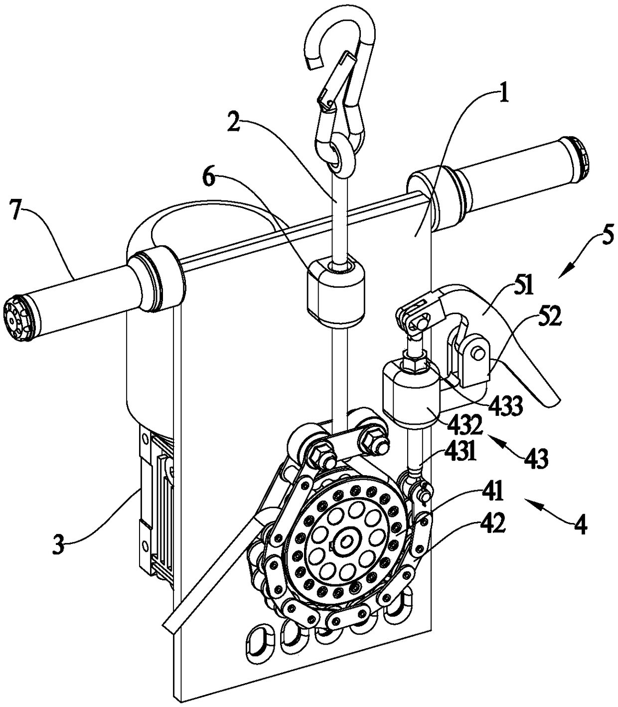
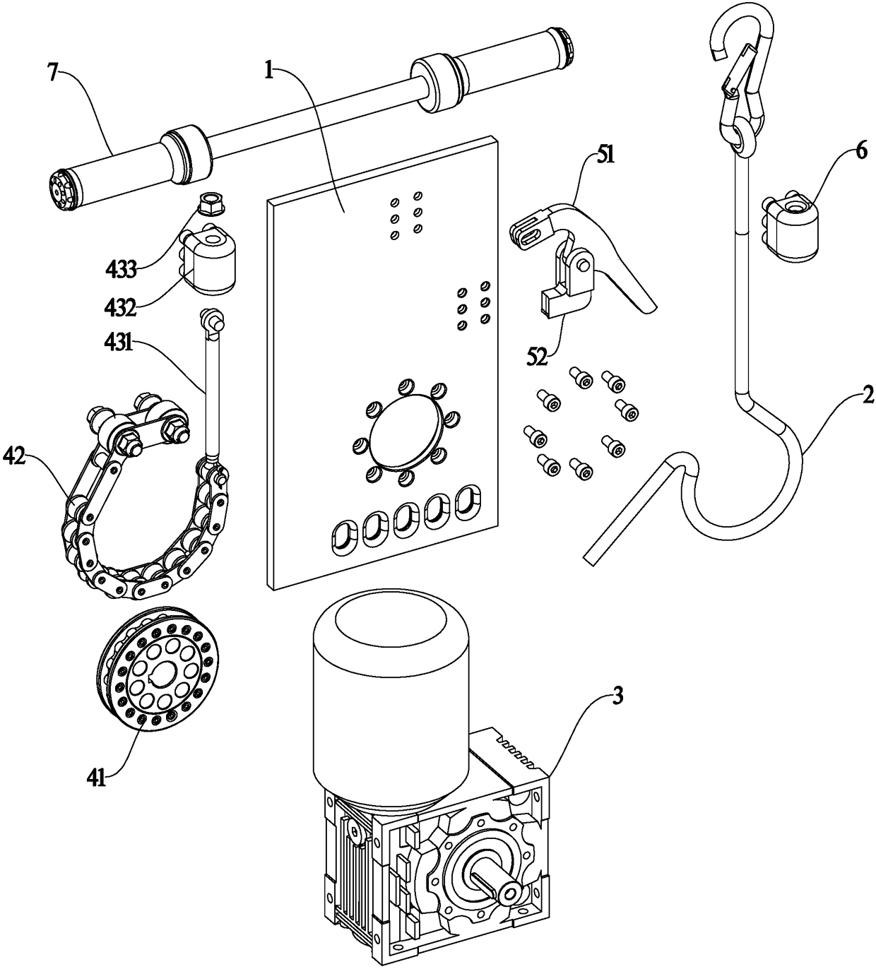
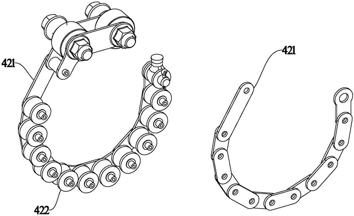
[0035] Such as Figure 1~6As shown, a preferred embodiment of the radial pressing mechanism 4 in the present invention includes a rotating disk 41 and a pressing member 42. The pressing member 42 is a chain structure, including a chain plate 421 and a roller 422. The chain plate 421 is hinged in turn, and the roller 422 is hinged between the chain plates 421 on both sides, the two ends of the pressing member 42 are fixed, and the pressing member 42 surrounds the periphery of the turntable 41 along the circumferential direction of the turntable, and the rope 2 passes between the turntable 41 and the pressing member 42, A plurality of rollers 422 press the rope 2 to contact the turntable 41; when the turntabl...


PUM


Abstract

The invention provides a radial pressing mechanism. The radial pressing mechanism comprises a rotating disc and a pressing part; the pressing part is of a chain structure and comprises chain plates and idler wheels; the chain plates are sequentially articulated; the idler wheels are articulated between the chain plates positioned at the two sides; the two ends of the pressing part are fixed and are arranged at the periphery of the rotating disc; a rope penetrates through the position between the rotating disc and the pressing part; the rope is pressed by the idler wheels so as to make contactwith the rotating disc; when the rotating disc runs on the rope, the rope is used for driving the idler wheels to rotate; the invention also provides a lifting device; the lifting device comprises a frame, the rope, a power mechanism and the radial pressing mechanism; the radial pressing mechanism has the advantages of simple structure, small abrasion, little generated heat, long service life andreliable pressing; and the lifting device comprising the radial pressing mechanism has the advantages of being simple in structure, safe, reliable and long in service life.

Description

technical field [0001] The invention relates to the field of mechanical equipment, in particular to a pressing mechanism and a lifting device. Background technique [0002] The lifting device is a device that enables people or things to move back and forth between low and high places. The important indicators of the lifting device are: 1. Safety; 2. Detachability; 3. Has the function of crisis relief and escape. [0003] At present, the common lifting mechanisms include civil elevators and building elevators. Civilian elevators have high requirements for supporting facilities, and generally cannot be used for outdoor operations; cables are used for lifting, and cable breakage is prone to fall accidents. In addition, power failure during operation is not conducive to escape. Construction lifts are suitable for outdoor use, but steel pipe supports are required, making the construction relatively complex and costly. At the same time, construction lifts are lifted by cables, wh...

Claims


Application Information

Patent Timeline
Patent Type & Authority Applications(China)
IPC IPC(8): B66D1/14B66D5/24
CPCB66D1/14B66D5/24
Inventor 赖建防吕伟宏
Owner 浙江弘安智能科技有限公司
Why Eureka
Try Eureka