Concrete test piece forming die capable of adjusting steel bar position and forming method

A technology for the location of concrete specimens and steel bars, which is applied to molds, ceramic molding machines, mold fixing devices, etc., and can solve problems such as difficult fixing of long side plates and unstable fixing of steel bars

Active Publication Date: 2018-07-10
CHINA RAILWAY TUNNEL GROUP CO LTD +2
View PDF8 Cites 10 Cited by
  • Summary
  • Abstract
  • Description
  • Claims
  • Application Information

AI Technical Summary

Problems solved by technology

The preparation of the existing reinforced concrete test blocks usually uses pads or simple molds to fix the position of the steel bars. The former will cause instability in the fixing of the steel bars during the pouring and vibration process, while the latter is only applicable to the case of a single steel bar spacing. Dies often need to be changed after rebar diameter or rebar spacing
In addition, the commonly used iron molds are not easy to fix because of their long side plates, so two people are often needed to cooperate in the assembly process to quickly assemble

Method used


Image

  • Concrete test piece forming die capable of adjusting steel bar position and forming method
  • Concrete test piece forming die capable of adjusting steel bar position and forming method
  • Concrete test piece forming die capable of adjusting steel bar position and forming method

Examples


Embodiment Construction

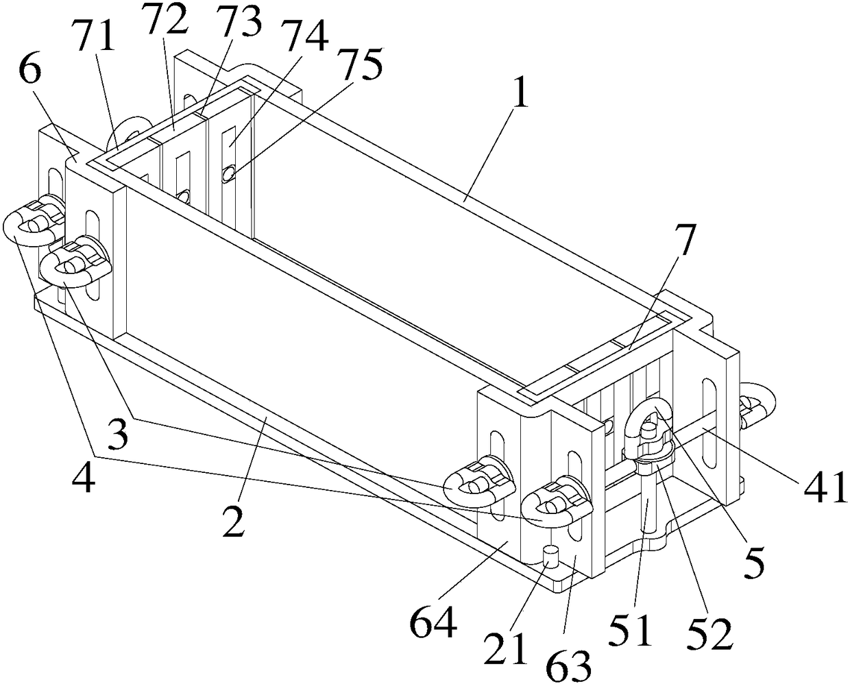
[0083] Such as Figure 1-9 As shown, the embodiment of the present invention provides a concrete specimen forming mold capable of adjusting the position of steel bars, including a bottom plate 2, two opposite side plates 1 and two opposite end plates 7, the side plates 1 and the end plate 7 are fixed around the bottom plate 2, so that the side plate 1, the end plate 7 and the bottom plate 2 enclose a cavity with an open top for forming a concrete specimen,

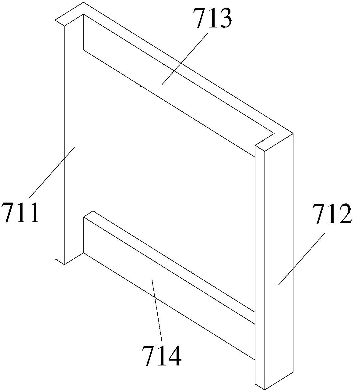
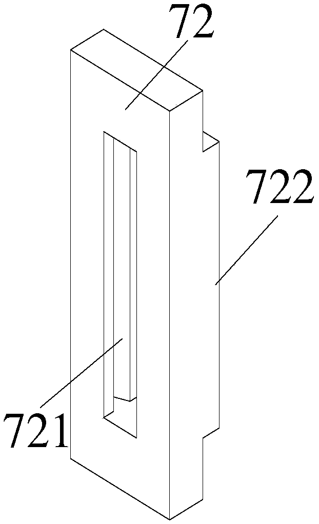
[0084] The end plate 7 includes an end plate support 71 and a T-shaped adjustment area, and the end plate support 71 is composed of an upper frame 713 extending along the X-axis direction, a lower frame 714 and a left frame 711 extending along the Y-axis direction 1. The right frame 712 encloses a structure with a cavity in the middle. The T-shaped adjustment area includes an adjustment area base 81 and an adjustment area boss 82 protruding from one side of the adjustment area base 81. The adjustment area boss 82 insertin...


PUM

PropertyMeasurementUnit
thicknessaaaaaaaaaa

Abstract

The invention relates to a concrete test piece forming die capable of adjusting a steel bar position and a forming method. The forming die comprises a bottom plate, two opposite side plates and two end plates arranged oppositely, and the side plates and the end plates are fixed on the periphery of the bottom plate; the end plates comprises end plate supports and T-shaped adjusting regions, and theT-shaped adjusting regions comprises adjusting area bases and adjusting area bosses extending from one sides of the adjusting area bases; the adjusting area bosses are inserted into the cavities of the end plate supports in the Z-axis direction, and end plates with basically flat inner sides are formed; the T-shaped adjusting regions are formed by connecting a plurality of T-shaped positioning pieces arranged in the X-axis direction in parallel, or through the T-shaped positioning pieces and T-shaped clamping plates arranged and matched at intervals in the X-axis direction; and the middle parts of the T-shaped positioning pieces are provided with reinforcing steel bar positioning holes with axes arranged in the Z-axis direction, and the steel bar positioning holes of the two oppositely-arranged end plates are arranged correspondingly.

Description

technical field [0001] The invention relates to a concrete test piece forming mold and a forming method capable of adjusting the position of steel bars. Background technique [0002] Reinforced concrete structure is the most widely used structural form in civil and hydraulic engineering, but in actual engineering, reinforced concrete structure often leads to structural damage due to the structure itself and the surrounding environment, which in turn causes huge economic losses and safety Hidden danger. In order to analyze the failure mechanism of reinforced concrete structures, it is necessary to prepare reinforced concrete test blocks in the laboratory, and conduct related experiments and research on the test blocks. The preparation of the existing reinforced concrete test blocks usually uses pads or simple molds to fix the position of the steel bars. The former will cause instability in the fixing of the steel bars during the pouring and vibration process, while the latte...

Claims


Application Information

Patent Timeline
Patent Type & Authority Applications(China)
IPC IPC(8): B28B7/00B28B7/02B28B23/02
CPCB28B7/0002B28B7/0014B28B7/02B28B23/02B28B23/024
Inventor 戴上秋刘加平田倩
Owner CHINA RAILWAY TUNNEL GROUP CO LTD
Why Eureka
Try Eureka