Medical transferring bed

A transfer bed and flexible belt technology, applied in medical transportation, hospital beds, medical science, etc., can solve the problems of patients with large range of body movement, reduced gravity, and increased strength of guide rollers, so as to reduce the risk of secondary injuries , the risk of secondary injury is low, and the effect of reducing the safety distance

Inactive Publication Date: 2018-07-20
浙江佑仁智能机器人有限公司 +1
View PDF3 Cites 2 Cited by
  • Summary
  • Abstract
  • Description
  • Claims
  • Application Information

AI Technical Summary

Problems solved by technology

But in the actual use process, the part of the conveyor belt 38 in the above-mentioned robot positioned between the two guide rollers must be sunken when it is subjected to the gravity of the patient.
Therefore, it is required to leave enough distance between the conveyor belt and the running mechanism below to avoid interference between the concave conveyor belt and the running mechanism, which leads to a larger dimension of the robot along the thickness direction, and when this The thicker robot gradually penetrates into the gap between the patient's back and the bed surface, so that when the patient is raised, it will inevitably lead to a larger range of motion of the patient's body, which obviously cannot reduce the patient's body weight during the transfer process. The purpose of reducing the risk of secondary injury by reducing the range of motion
[0003] In addition, ordinary technicians in the industry also consider adopting a conveyor belt with little ductility, but although this conveyor belt has a small concave range when carrying a patient with the same weight, the force on the guide rollers for supporting the conveyor belt will be greatly increased. increase, so the strength requirement for the guide roller increases
On the other hand, the gravity of the guide roller assembly with the same structure and material will be greatly reduced through this type of conveyor belt, which obviously cannot meet the needs of carrying patients

Method used


Image

  • Medical transferring bed
  • Medical transferring bed
  • Medical transferring bed

Examples


Embodiment 1

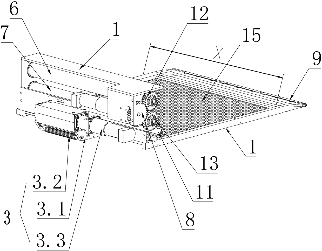
[0063] The invention provides a transfer bed for medical care, which includes such as figure 1 or Figure 7 Shown frame 1 and flexible belt 2, flexible belt 2 is arranged on the frame 1, and the bottom of frame 1 is provided with running gear 3, is used to drive frame 1 to move, and the top of described running gear is provided with for bearing The working area of ​​the patient, the part of the flexible belt located in the working area is tightened to form a supporting surface for lifting the patient, and it is characterized in that it also includes an equipment installation area outside the working area. A drive roller assembly is provided in the equipment installation area, and a guide roller assembly is provided on the side away from the equipment installation area in the working area. The drive roller assembly and the guide roller assembly cooperate with each other to drive the The flexible belt outside the assembly and the guide roller assembly moves along its own length...

Embodiment 2

[0067] The driving roller assembly includes a driving shaft, and the driving shaft rotates with the frame 1 along the circumference of its own axis, and the guide roller assembly includes a front roller 9, and the above-mentioned flexible belt 2 is wound around the outside of the driving roller assembly Winding the flexible belt 2 around the outside of the guide roller assembly means that the inner side walls of the flexible belt 2 are respectively placed outside the drive shaft and the front roller 9, and the flexible belt is in a tight state, and the flexible belt 2 is located in the working area 5 The part of the flexible belt 2 is tightened to form a platform 2.1 for carrying the patient. The structure of the flexible belt 2 located on the part of the platform 2.1 is a double-layer flexible belt structure. The upper area of ​​the upper flexible belt 2.2 forms a transfer space 10 for accommodating the patient. The equipment installation area is provided with a drive transfer...

Embodiment 3

[0079] The walking unit includes a walking support 3.1, which is fixed on the bottom of the frame 1, and a plurality of mutually parallel rolling shafts are arranged at intervals along the horizontal direction on the walking support 3.1, and the described frame 1 or walking The support 3.1 is provided with a travel driver 3.3 for driving the rotation of the rolling shaft.

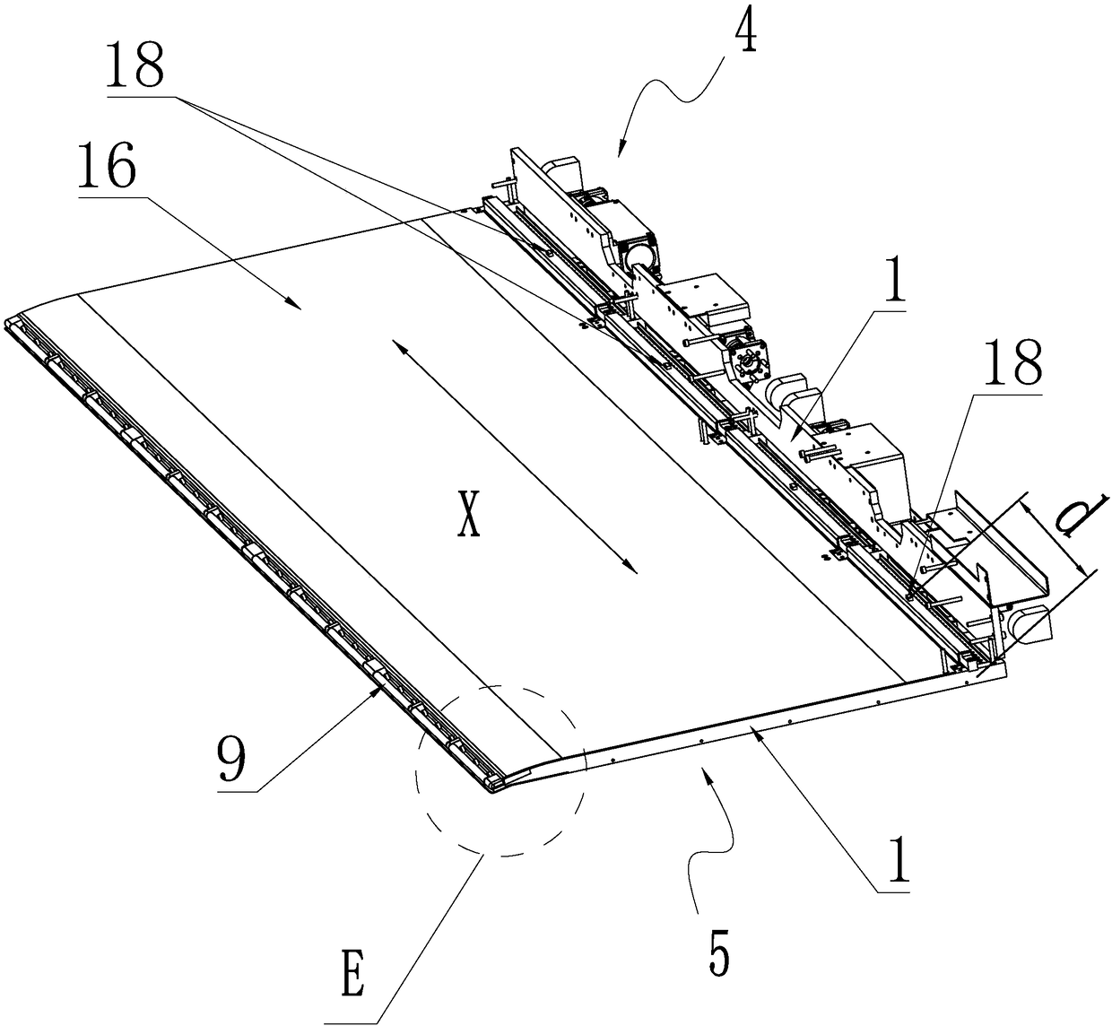
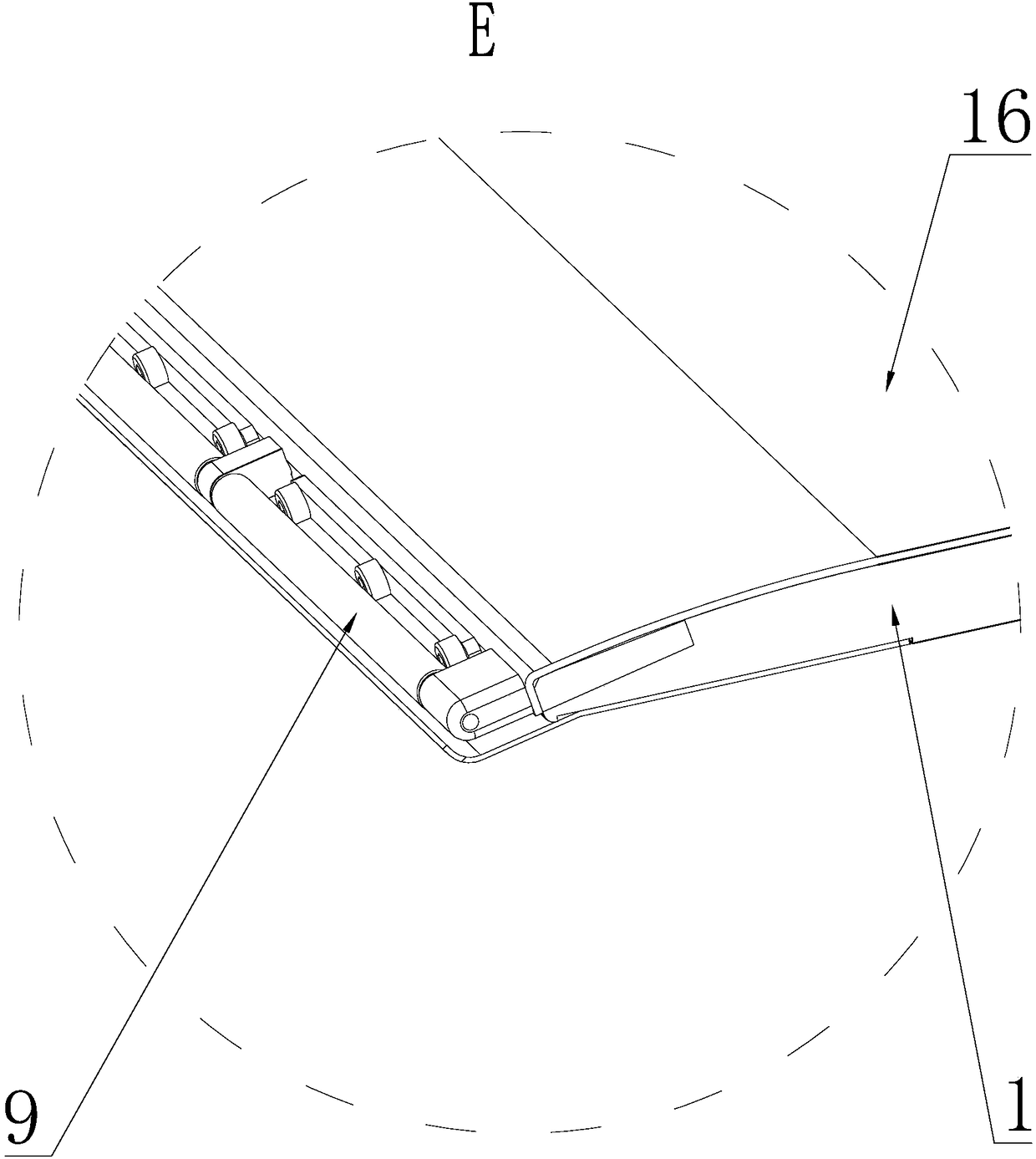
[0080] Such as Figure 16 to Figure 23 As shown in any view in , there are multiple flexible belts 2, and the multiple flexible belts 2 are sequentially arranged at intervals along the width direction X of the rack 1, and the equipment installation area 4 is located in the corresponding flexible belt 2 The corresponding upper rollers 6, lower rollers 7 and transfer drivers 8 are provided at the corresponding positions, and the corresponding front rollers 9 are provided at the corresponding positions of the flexible belts 2 in the working area 5.

[0081] Embodiment 1 as the transport driver 8:

[0082] Su...


PUM


Abstract

The invention discloses a medical transferring bed. The medical transferring bed comprises a machine frame, and flexible belts and transferring drivers for driving the flexible belts to move in the length direction of the flexible belts are arranged on the machine frame. The medical transferring bed is characterized in that front rollers are arranged on the machine frame, the parts, close to the front rollers, of the flexible belts are wound around through the front roller to form a dual-layer structure, a supporting plate is arranged between upper flexible belt bodies and lower flexible beltbodies, and is fixed to the machine frame, and the supporting plate lifts the upper flexible belt bodies when the upper flexible belt bodies suffer from external force to be concave. The medical transferring bed is large in carrying capacity, the size in the thickness direction when the medical transferring bed is required to be put into the back of a patient is small, and therefore in the patienttransferring process, the movement range of the patient can be small.

Description

technical field [0001] The invention relates to the technical field of medical auxiliary equipment, in particular to a transfer bed for medical care. Background technique [0002] In related technologies, it is necessary for a patient with limited mobility or unconsciousness to move between different beds with the help of external personnel or external equipment. Although the method of lifting by external personnel can quickly move the patient, it is very difficult for the personnel to move during the lifting process. It is easy to cause secondary injury to patients, especially for critically ill patients. Therefore, with the development of the industry, external equipment used for patient transfer has become an inevitable trend in the development of the industry. For example, the patent name is the invention patent application for a two-way transfer nursing robot (patent application number is 201611218398.1). The working principle of this prior art transfer nursing robot i...

Claims


Application Information

Patent Timeline
Patent Type & Authority Applications(China)
IPC IPC(8): A61G7/10
CPCA61G7/1032A61G7/1065A61G7/1073A61G2203/70
Inventor 王旭升王洪波桑凌峰石少华甘中学
Owner 浙江佑仁智能机器人有限公司
Why Eureka
Try Eureka