Handheld Electric Tape Dispenser

A tape cutting, handheld technology, applied in the direction of thin material processing, sending objects, transportation and packaging, etc., can solve the problems of inaccurate cutting and distribution, low production efficiency, etc.

Active Publication Date: 2019-10-15
蔡凯彦
View PDF12 Cites 0 Cited by
  • Summary
  • Abstract
  • Description
  • Claims
  • Application Information

AI Technical Summary

Problems solved by technology

[0003] The main problem with current handheld tape cutters is the need to manually tension and stretch the tape to variable lengths before manually disconnecting the cutter, resulting in low productivity and imprecise cut distribution

Method used


Image

  • Handheld Electric Tape Dispenser
  • Handheld Electric Tape Dispenser
  • Handheld Electric Tape Dispenser

Examples


Embodiment Construction

[0104] Embodiments of the present invention will be described in detail below in conjunction with the accompanying drawings.

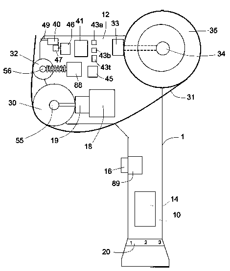
[0105] Such as figure 1 As shown, the present invention provides a hand-held electric tape cutter 1 , which includes a handle 10 and a frame 12 mounted on the handle 10 . The outer casings (not shown) of the handle 10 and frame 12 have been removed to reveal the inner structure. The handle 10 is in the shape of a shaft suitable for holding, and accommodates a set of batteries 14 , buttons 16 and a speed controller 20 . Further, the handle can also accommodate electronic circuit boards, switches, motors and gear components. The main structure of frame 12 includes main roller 30, switching roller 35, auxiliary roller 32, cutter 40, switches, electronic circuit board, motor and gear components. The handle 10 and frame 12 are available in various designs, sizes and shapes for the purpose of securing the components of the tape cutter 1 . The motor 18 an...


PUM


Abstract

The invention discloses a hand-held electric tape cutter, which is controlled by the bonding of a surface trigger device, a main trigger device and electrical components during the adhesive tape sticking and cutting processes. The invention has the advantages that the triggering efficiency is effectively improved by adding the fixing device and the holding device; the adhesive tape for packaging can be automatically distributed and cut, and the efficiency is high.

Description

technical field [0001] The present invention relates to a tape cutter, and more particularly to an electrically driven, hand-held tape cutter having means for dispensing and cutting tape at a desired speed. Background technique [0002] The present existing adhesive tape cutter is a replacement product of the prior art US5236540A. The tape cutter includes a tape device, a rotating roller, a pressing device and an elastic element. Wherein, the adhesive tape device includes a rotatable part supported on the frame for supporting the adhesive tape; the rotating roller is supported on the frame; the pressing device includes a handle extending downward through the bottom slot of the frame and a Panels engaged by rotating rollers; the elastic element used to bias the panel of the lamination device towards the rollers to hold the tape in place, the panels can be separated from the rotating rollers when the handle of the lamination device is placed against the elastic elements . ...

Claims


Application Information

Patent Timeline
Patent Type & Authority Patents(China)
IPC IPC(8): B65H35/07
Inventor 蔡凯彦
Owner 蔡凯彦
Why Eureka
Try Eureka