
Waist knee support device for seat
A supporter, waist and knee technology, applied in chairs, applications, home appliances, etc., can solve problems such as inability to use
- Summary
- Abstract
- Description
- Claims
- Application Information
AI Technical Summary
Problems solved by technology
Method used
Image

Examples
Embodiment Construction
[0009] The specific embodiments of the present invention will be described in detail below in conjunction with the technical solutions and accompanying drawings.
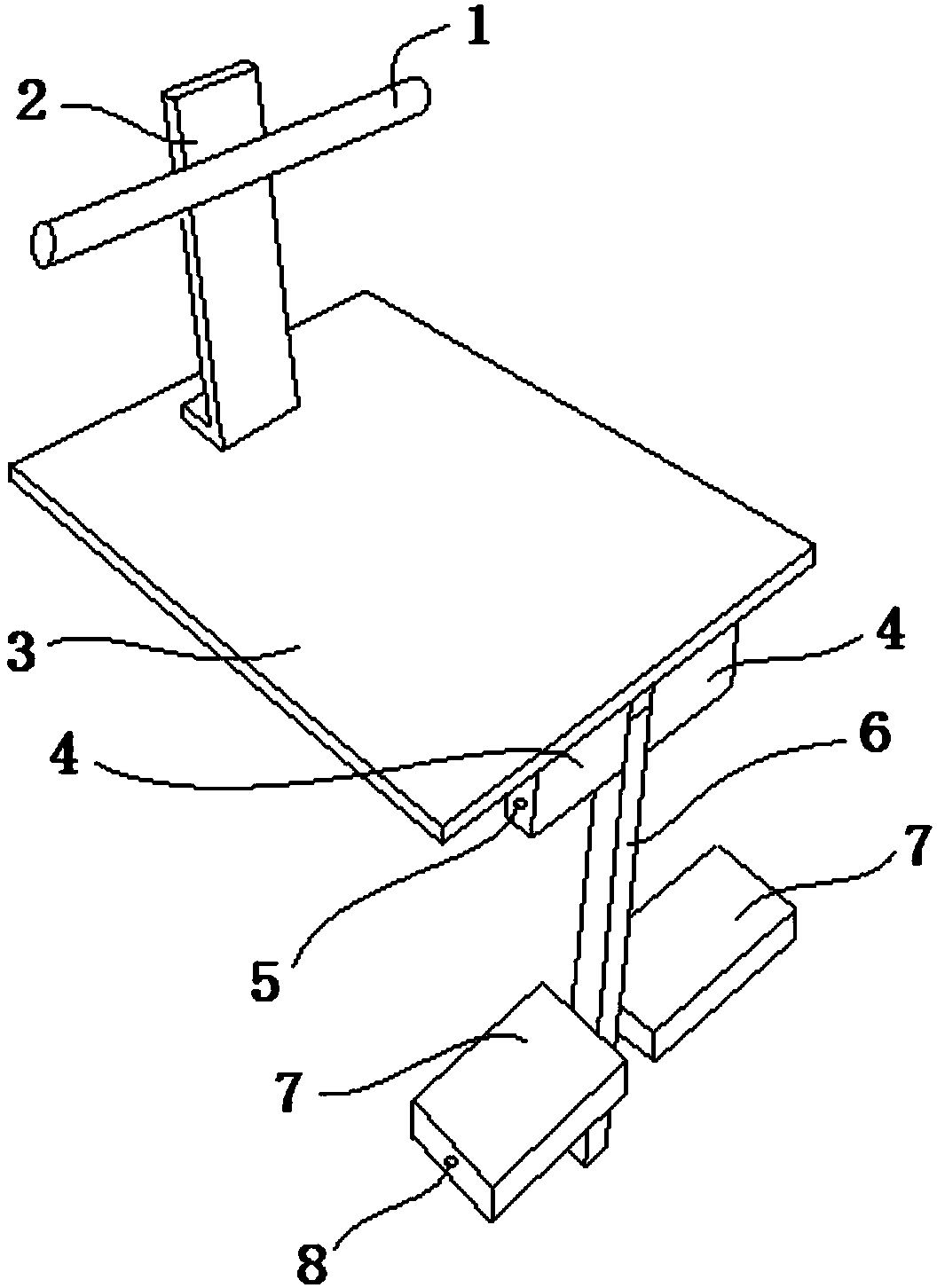
[0010] Such as figure 1 As shown, the leaning bar 1 is fixed on the upper part of the leaning plate 2, the lower end of the leaning plate 2 is fixed on the rear of the seat plate 3, the front portion of the seat plate 3 is fixedly connected with the cushion block 4, and the middle part of the cushion block 4 has a hole. The upper and lower parts of the rod 6 have holes, and the middle part of the knee plate 7 has a hole. The first pin shaft 5 passes through the hole on the upper part of the connecting rod 6 and the center hole of the spacer 4, and the second pin shaft 8 passes through the lower part of the connecting rod 6. The hole and the center hole of the knee plate 7. The connecting rod 6 has a degree of freedom to rotate around the first pin shaft 5 relative to the spacer 4 , and the knee plate 7 has a degree...
PUM
 Abstract
Description
Claims
Application Information