Novel lightweight electromagnetic self-piercing riveting gun

A lightweight, self-piercing riveting technology, which is applied in the field of electromagnetic riveting equipment and riveting equipment, can solve the problems of seldom research on portable electromagnetic self-piercing riveting guns, riveting recoil cannot be offset, and the structure of the riveting system is complex, etc., to achieve shock absorption effect Obvious effect of increased forming force and low control cost

Pending Publication Date: 2018-09-28
HUBEI BOSHILONG TECH
View PDF2 Cites 8 Cited by
  • Summary
  • Abstract
  • Description
  • Claims
  • Application Information

AI Technical Summary

Problems solved by technology

At present, my country has only developed some fixed and portable electromagnetic riveting guns, and there is little research on portable electromagnetic self-piercing riveting guns.
Moreover, the solenoids used in these electromagnetic riveting guns have defects such as excessive inductive reactance and small discharge current.
Such as patent application CN105903884A, which will result in small forming force and poor heat dissipation
In addition, the existing equipment has the defects and disadvantages of poor riveting quality consistency, high labor intensity, complex structure of the riveting system, high production cost, the applicable object is only the connection of some simple structure workpieces, and the recoil force causes great harm to the operator. It is very limited in practical application
At the same time, such as the patented CN101817056A handheld electromagnetic self-piercing riveting gun, there are problems such as not easy to control, riveting recoil cannot be offset, making the riveting gun difficult to operate, etc.

Method used


Image

  • Novel lightweight electromagnetic self-piercing riveting gun
  • Novel lightweight electromagnetic self-piercing riveting gun
  • Novel lightweight electromagnetic self-piercing riveting gun

Examples


Embodiment Construction

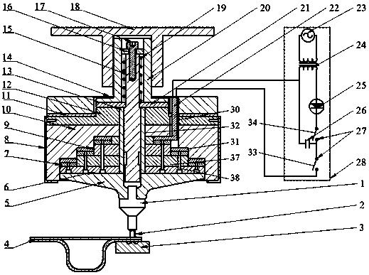
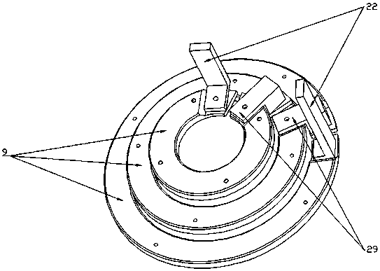
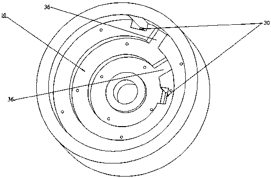
[0031] Depend on figure 1 As shown, a new lightweight electromagnetic self-piercing riveting gun includes a punch 1, an amplifier 5, a driver plate carrier 37, a driver plate 7, a shell 8, a coil 9, a coil carrier 10, a rubber cushion 11, and a fixing plate 12. Guide rod sleeve 13, buffer block 14, guide rod 15, spring upper pressure block 16, connection seat 18, return spring 19, guide cylinder 20, spring lower pressure block 21, electromagnetic equipment 28, connector 29, terminal 22. Compression screw 17 and die 3, the coil carrier 10 is fixedly installed on the bottom of the fixed plate 12, the rubber buffer pad 11 is fixedly installed on the fixed plate 12, and the buffer block 14 is fixedly installed on the rubber buffer pad 11, the buffer block 14 can adopt No. 45 steel material. Depend on Figure 12 As shown, the spring lower pressure block 21 is fixedly installed on the fixed plate 12, by Figure 13 As shown, the guide cylinder 20 is fixedly installed on the spring...


PUM


Abstract

The invention discloses a novel lightweight electromagnetic self-piercing riveting gun. According to the riveting gun, a coil carrier is fixedly arranged at the bottom of a fixing plate; a rubber cushion pad is fixedly arranged on the fixing plate; a buffer block is fixedly arranged on the rubber cushion pad; a spring pressing block is fixedly arranged on the fixing plate; a guide cylinder is fixedly arranged on the spring pressing block; a connecting seat is fixedly arranged on the upper part of the guide cylinder; ring grooves are distributed in the lower part of the coil carrier in a ladderform; electrically-connected coils are shaped like rings corresponding to the ring grooves and are respectively fixedly arranged in the ring grooves; and guiding holes are formed in the fixing plateand the coil carrier. The riveting gun disclosed by the invention has that advantages that the structure is simplified; the manufacturing cost is reduced; the frequency and the magnitude of currents are increased; the forming force is increased; the shock absorption effect is obvious; the recoil force is remarkably reduced; the consistency of workpiece riveting is well guaranteed; and the rivetinggun is suitable for production lines for automatically connecting workpieces.

Description

technical field [0001] The present invention relates to the technical field of riveting equipment, more specifically to the technical field of electromagnetic riveting equipment. Background technique [0002] With the vigorous development of the automobile manufacturing industry in our country, the body connection technology of new energy vehicles is facing various challenges, especially the connection of dissimilar materials and metal materials. Electromagnetic self-piercing riveting technology is a plate joining technology that does not require pre-drilling and is especially suitable for dissimilar materials. With the irreplaceable advantages of traditional riveting and traditional self-piercing riveting in riveting difficult-to-form materials and composite materials, electromagnetic self-piercing riveting has broad application prospects in the field of automobile manufacturing. At present, my country has only developed some fixed and portable electromagnetic riveting gun...

Claims


Application Information

Patent Timeline
Patent Type & Authority Applications(China)
IPC IPC(8): B21J15/02B21J15/24
CPCB21J15/025B21J15/24
Inventor 程志毅崔俊佳蒋大胜张旭朱晓辉蒋洁刘军韩克平
Owner HUBEI BOSHILONG TECH
Why Eureka
Try Eureka