Cable multi-angle laying scaffold

A multi-angle, construction frame technology, which is applied in the direction of cable laying equipment, conveying filamentous materials, thin material processing, etc., can solve the problems of shaking and entanglement of the transmission frame, and achieve the effect of eliminating damage to the cable

Active Publication Date: 2018-10-26
湘潭潭州电力建设有限公司
View PDF11 Cites 13 Cited by
  • Summary
  • Abstract
  • Description
  • Claims
  • Application Information

AI Technical Summary

Problems solved by technology

[0004] In order to solve the above problems, the present invention provides a cable multi-angle laying construction frame, which can solve the problems that the existing cable frame will cause friction with the side wall of the cable well and the cable will be entangled on the cable well escalator when the cable is paid out. Hidden dangers, cables will be entangled when they are transmitted in two directions, and the transmission frame will shake when the cables are transmitted in the cable well; it can realize the function of adjustable angle transmission of the cable in the cable well, and the cable will not interfere with the cable well. There is friction on the side wall, there is no hidden danger that the cable will be entangled on the cable shaft escalator, the cable will not be entangled when it is transmitted in two directions, and the transmission frame will not shake when the cable is transmitted in the cable shaft, etc.

Method used


Image

  • Cable multi-angle laying scaffold
  • Cable multi-angle laying scaffold
  • Cable multi-angle laying scaffold

Examples


Embodiment Construction

[0023] In order to make the technical means, creative features, goals and effects achieved by the present invention easy to understand, the present invention will be further described below in conjunction with specific illustrations. It should be noted that, in the case of no conflict, the embodiments in the present application and the features in the embodiments can be combined with each other.

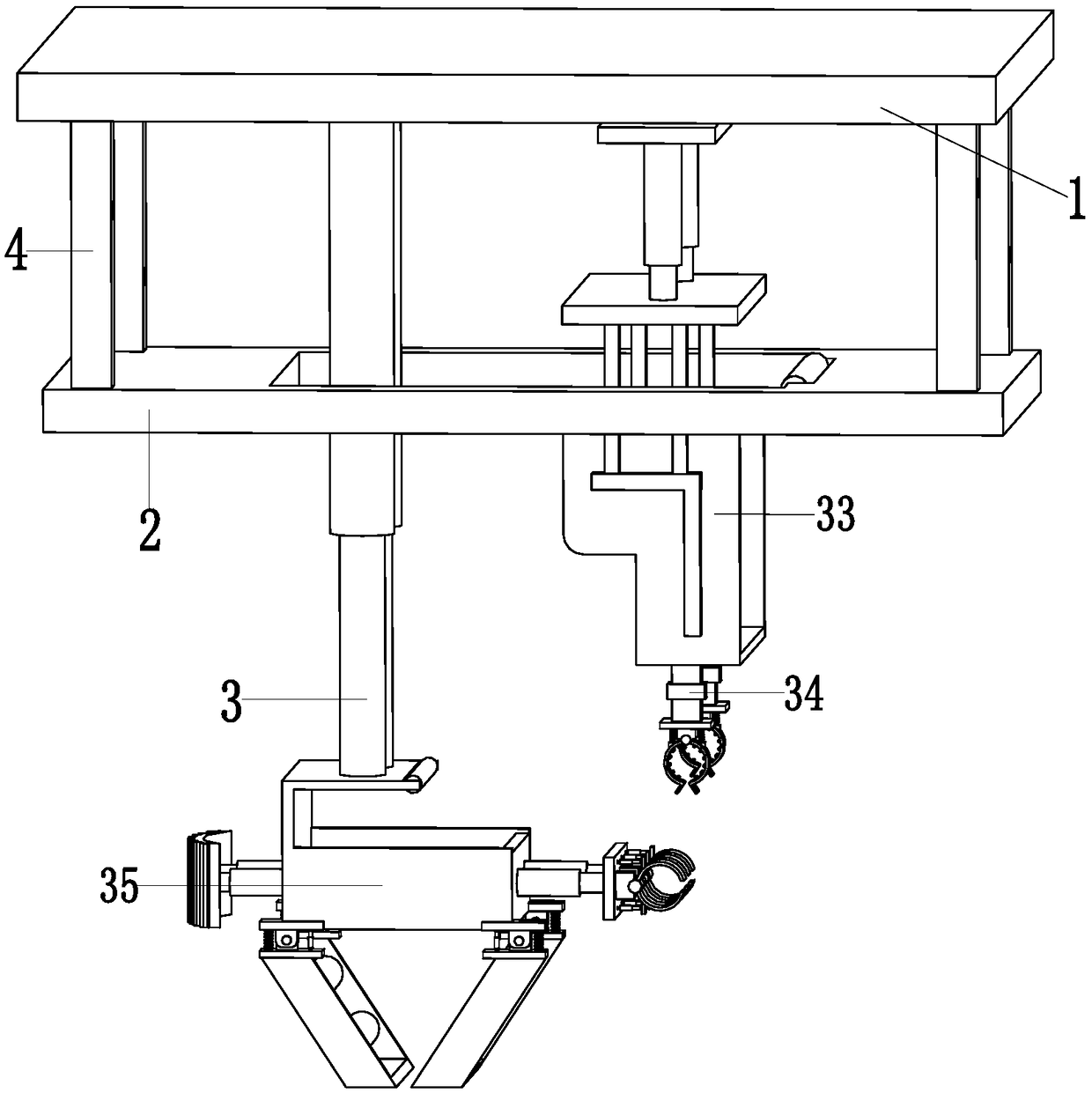
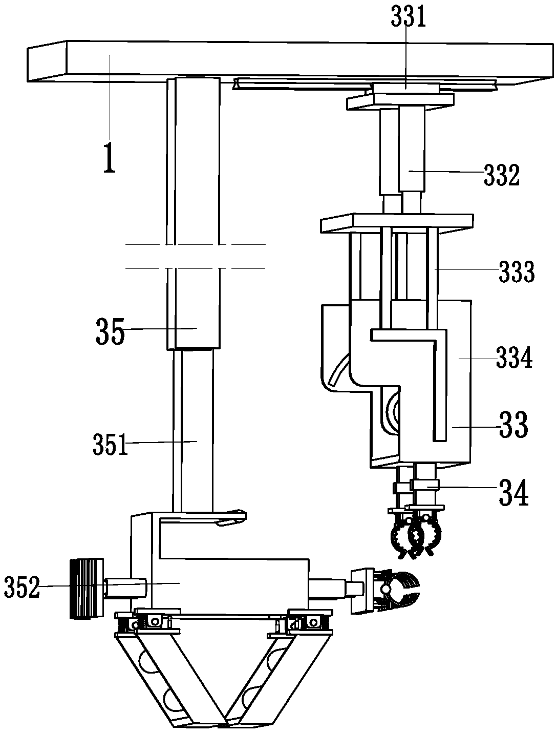
[0024] Such as Figure 1 to Figure 6 As shown, a cable multi-angle laying construction frame includes a supporting top plate 1, a supporting bottom plate 2, a wire release device 3 and a supporting connecting column 4, and the middle part of the supporting bottom plate 2 is provided with a square groove, and the supporting bottom plate 2 is square. The left side wall of the groove is provided with rotating rollers, and the rotating rollers provided on the square groove of the support base plate 2 can prevent the cables from rubbing against the support base plate 2, and the support to...


PUM


Abstract

The invention relates to a cable multi-angle laying scaffold. The cable multi-angle laying scaffold comprises a support roof, a support bottom plate, a paying-off device and a support connecting column; a square slot is arranged in the middle part of the support bottom plate, the support roof is arranged on the top of the support bottom plate through the support connecting column, and the paying-off device is connected with the bottom of the support roof; the paying-off device comprises a guiding mechanism, a clamping mechanism and a distributing mechanism; the clamping mechanism comprises a clamping telescopic column, a clamping connecting rack, a clamping claw and a clamping spring. The problems that the cable can produce friction with the sidewall of a cable well when the existing cablerack performs the cable pay-off, the cable has the hidden danger of twisting on the escalator of the cable well, the twining can occur when the cable is conveyed in two directions, and a transmissionrack can shake when the cable is conveyed in the cable well can be solved, and the function of performing angle-adjustable conveying of the cable in the cable well can be realized.

Description

technical field [0001] The invention relates to the technical field of electric power construction, in particular to a cable multi-angle laying construction frame. Background technique [0002] For the sake of the beauty of the city, bid farewell to the era of utility poles on the road. Now a large number of cables are conducted through underground cable wells. Now the city's infrastructure, subways, water pipes, etc. are basically underground, so the depth of the cable wells is also The deeper Larger and deeper cable wells will be equipped with escalators on their side walls to facilitate construction personnel to go up and down. The top of the cable well is equipped with a circular cable cover to reduce rainwater pouring into the cable well. [0003] The guide device in the cable well will be added when the deeper cable well is laid out, but this kind of guide device generally does not extend to the lower end of the cable well, so that the cable payout efficiency is low an...

Claims


Application Information

Patent Timeline
Patent Type & Authority Applications(China)
IPC IPC(8): H02G1/06B65H49/32B65H57/14
CPCB65H49/324B65H57/14H02G1/06
Inventor 郑文豪
Owner 湘潭潭州电力建设有限公司
Why Eureka
Try Eureka